
Virtual optical network mapping method and device combining energy consumption and load balancing

A technology of virtual network mapping and virtual optical network, applied in multiplexing system selection devices, energy consumption reduction, selection devices, etc. Node or link heavy load and other problems, to achieve the effect of reducing energy consumption, reducing energy consumption, and balancing the overall load

Active Publication Date: 2019-06-14
CHONGQING UNIV OF POSTS & TELECOMM +2
View PDF10 Cites 13 Cited by
  • Summary
  • Abstract
  • Description
  • Claims
  • Application Information

AI Technical Summary

Problems solved by technology

However, the blind pursuit of energy saving will cause some nodes or links in the underlying network to be in a heavy load state, resulting in bottleneck nodes or links, which will reduce the reception rate of virtual optical network requests to a certain extent.
[0006] Since the energy-consuming equipment in the elastic optical network environment is complex and diverse (mainly including IP routers, transponders, optical cross-connectors, and optical amplifiers), and the virtual network mapping needs to follow the corresponding spectrum constraints in the elastic optical network, so in 2 / The virtual network mapping algorithm considering energy saving in the 3-layer network and WDM network scenarios cannot be directly applied to the elastic optical network, and it is urgent to find an efficient and energy-saving virtual network mapping method in the elastic optical network environment

Method used


Image

  • Virtual optical network mapping method and device combining energy consumption and load balancing
  • Virtual optical network mapping method and device combining energy consumption and load balancing
  • Virtual optical network mapping method and device combining energy consumption and load balancing

Examples


Embodiment Construction

[0055] Embodiments of the present invention are described below through specific examples, and those skilled in the art can easily understand other advantages and effects of the present invention from the content disclosed in this specification. The present invention can also be implemented or applied through other different specific implementation modes, and various modifications or changes can be made to the details in this specification based on different viewpoints and applications without departing from the spirit of the present invention. It should be noted that the diagrams provided in the following embodiments are only schematically illustrating the basic concept of the present invention, and the following embodiments and the features in the embodiments can be combined with each other in the case of no conflict.

[0056] Among them, the figures are only for illustrative purposes, and what are shown are only schematic diagrams rather than physical figures, and should not...


PUM


Abstract

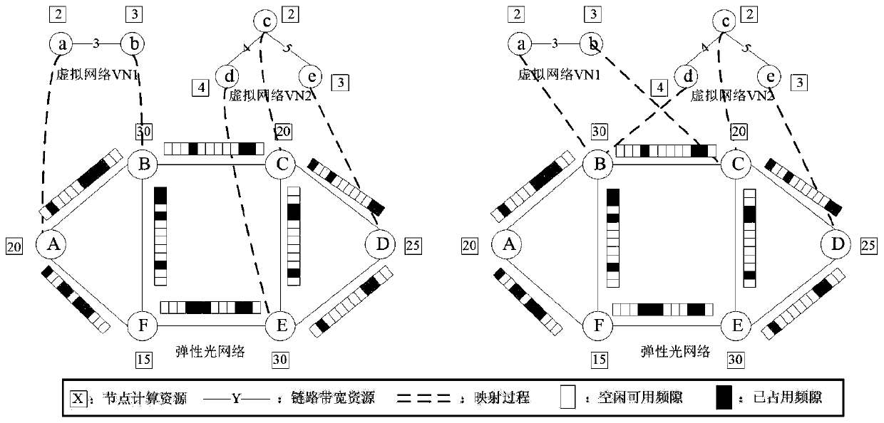
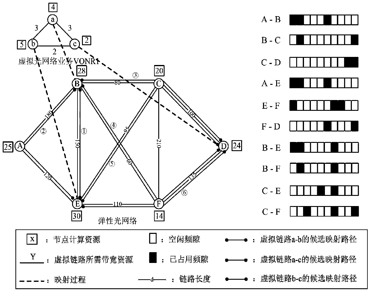
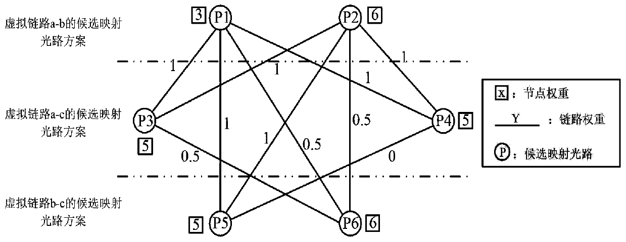
The invention relates to a virtual optical network mapping method and device combining energy consumption and load balancing, and belongs to the technical field of electric power communication and optical communication. According to the method, in the node mapping stage of a data virtual request, the length of adjacent links of physical nodes, the difference between calculation resources of the nodes and bandwidth resources of the adjacent links of the nodes are comprehensively considered, weight sorting is carried out on the physical nodes, and the mapping physical nodes of the virtual nodesare determined. In the virtual link mapping stage, the spectrum resource state of a physical optical path and loads on all links are comprehensively considered, a path resource matching degree formulais designed to select K candidate mapping optical paths for the virtual link, and a single-path mapping strategy based on the maximum cluster is provided on the basis to determine the mapping opticalpath of the virtual link. When available spectrum resources on a single physical optical path cannot meet the bandwidth resource requirement of a virtual link, a multi-path mapping strategy based ona link load mean value is adopted, and the network load is balanced while the energy consumption of equipment is reduced.

Description

technical field [0001] The invention belongs to the technical field of electric power communication and optical communication, and relates to a virtual optical network mapping method and device combining energy consumption and load balancing. Background technique [0002] In recent years, with the gradual expansion of the scale of power grid construction, the amount of relevant data in the power communication system has increased sharply, and the amount of power transmission and power consumption has also continued to increase. This has led to the fact that the original power information communication technology has been unable to meet the development of the times. Smart grid has gradually become the main direction of my country's power grid construction. By highly integrating advanced information technology, communication technology, computer technology, power electronics technology, renewable energy generation technology and original power transmission and distribution infr...

Claims


Application Information

Patent Timeline
Patent Type & Authority Applications(China)
IPC IPC(8): H04Q11/00H04L12/803H04L12/729H04L12/24H04L45/125
CPCY02D30/50
Inventor 刘焕淋杜君丹陈勇向敏马跃张少军杨斌杨琦张佳乐
Owner CHONGQING UNIV OF POSTS & TELECOMM
Learn More