A new type of high-efficiency continuous concentrator

A concentrator, high-efficiency technology, applied in solid separation, chemical instruments and methods, wet separation, etc., can solve the problems of unexplained shut-off valve, automatic valve reset of valve body, and water-dispersed expansion.

Active Publication Date: 2020-10-27
赣州金环磁选科技装备股份有限公司
View PDF6 Cites 0 Cited by
  • Summary
  • Abstract
  • Description
  • Claims
  • Application Information

AI Technical Summary

Problems solved by technology

[0004] The disadvantage of the above scheme is that the cut-off valve used does not specify what kind of valve body it is, and according to the traditional valve body on the market, it is a spring return structure. The valve can only be opened stably, but due to the centrifugal force, the divergent expansion of the water is caused. Whether the valve of the valve body can be automatically reset is a problem; The concentrate is produced by a sorting cycle. In the non-stop state, the valve is opened and the concentrate is discharged. The real-time injection of the ore to be selected and the concentrate may be mixed, and there may be a high probability that the two will be discharged at the same time. The problem

Method used


Image

  • A new type of high-efficiency continuous concentrator
  • A new type of high-efficiency continuous concentrator
  • A new type of high-efficiency continuous concentrator

Examples


Embodiment Construction

[0037] Below in conjunction with accompanying drawing and embodiment of description, specific embodiment of the present invention is described in further detail:

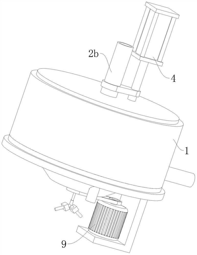
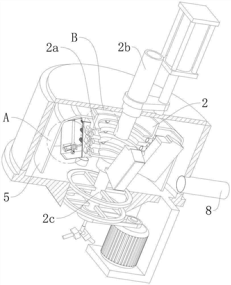
[0038] refer to Figure 1 to Figure 9 A new type of high-efficiency continuous concentrator is shown, including a main cylinder 1, a centrifugal drum 2, a feeding pipe 2b, an air supply system and a concentrate discharge system. The centrifugal drum 2 is installed vertically on the main Inside the cylinder 1, the centrifugal drum 2 is provided with a plurality of separation grooves 2a distributed along the axial interval, and the inner wall of each separation groove 2a is provided with a number of discharge discharge holes distributed equiangularly along the respective circumferential directions. A concentrate discharge pipe 3 is inserted in each discharge port, and a gate is installed at the downstream end of each concentrate discharge pipe 3. The concentrate discharge system includes several centrifugal rotors ins...


PUM


Abstract

The invention relates to the field of ore beneficiation equipment, in particular to a novel high-efficiency continuous ore beneficiation machine which comprises a main barrel, a centrifugal drum, a feed pipe, an air supply system and an ore concentrate drain-off system. The centrifugal drum is arranged in the main barrel; multiple separation grooves are formed in the centrifugal drum; multiple oreconcentrate discharge pipes are arranged on the inner walls of the separation grooves; open-close devices are arranged at the downstream ends of the ore concentrate discharge pipes; the ore concentrate drain-off system comprises multiple power pieces; the cross section of the centrifugal drum is in an inverted trapezoidal structure; the inclined direction of each power piece is the same as the inclined direction of a waist edge of the cross section of the centrifugal drum; each power piece is in transmission connection with the open-close device corresponding to the power piece; the feed pipeis arranged in the centrifugal drum; a hydraulic lifting system is arranged at the upper end of the feed pipe; the air supply system is arranged on the bottom part of a separation barrel; and the separation barrel is arranged on the periphery of the centrifugal drum. According to the novel high-efficiency continuous ore beneficiation machine provided by the invention, ore concentrates can be stably discharged in real time, and the simultaneous discharge rate of ores to be beneficiated and the ore concentrates is reduced.

Description

technical field [0001] The invention relates to the field of mineral processing equipment, in particular to a novel and efficient continuous mineral processing machine. Background technique [0002] The ore concentrator is mainly used for the beneficiation of gold, silver, tin, manganese, tungsten, iron, shaft, rare earth and other elements. As we all know, the current general-purpose discontinuous ore-discharging drum type centrifugal concentrator is the only thin-flow film concentrator that mainly relies on centrifugal force; modern centrifugal concentrators can be divided into two types, namely horizontal centrifugal concentrators and vertical centrifugal concentrators. Concentrator. The drum of the centrifugal concentrator rotates at a high speed at a certain number of revolutions, and the ore pulp is sent to the inner wall of the drum by the ore feeder through the feed nozzle in two places. The pulp rotates with the drum at high speed. Under the action of centrifugal ...

Claims


Application Information

Patent Timeline
Patent Type & Authority Patents(China)
IPC IPC(8): B03B5/48B03B11/00
Inventor 陈剑钱枝花饶宇欢陈亮亮狄家莲
Owner 赣州金环磁选科技装备股份有限公司
Why Eureka
Try Eureka