
A flexible loading and unloading method for CNC machine tools using a truss robot

A technology of CNC machine tools and robots, which is applied in the field of metal parts turning, can solve problems that affect the efficiency of processing operations, limited operating space, and reduce equipment compatibility, and achieve the effect of expanding the application range and continuous processing efficiency

Active Publication Date: 2020-07-03
UNIV OF SCI & TECH BEIJING
View PDF6 Cites 0 Cited by
  • Summary
  • Abstract
  • Description
  • Claims
  • Application Information

AI Technical Summary

Problems solved by technology

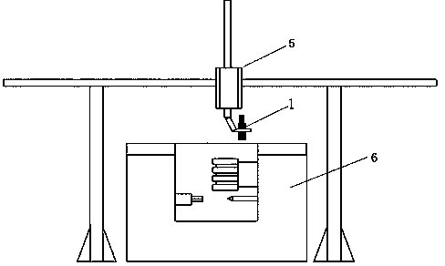
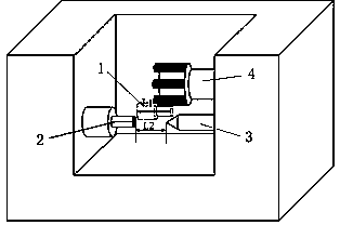
[0003] Since the truss robot belongs to the rectangular coordinate robot, it cannot be compared with the multi-degree-of-freedom joint robot in terms of space movement and positioning, especially in the limited operating space inside the CNC machine tool, the spindle chuck, tool holder and props, thimble, etc. inside the machine tool Both may interfere with the robot’s grippers and workpieces for loading and unloading. The loading and unloading action can be easily completed by manual operation, but it cannot be replaced by simple walking in Cartesian coordinates. As a result, the use of the truss robot will be affected by the size of the workpiece and the structure of the CNC machine tool. And the limitation of internal space size reduces the compatibility of equipment
In order to realize the loading and unloading action, sometimes the inside of the machine tool has to be modified, or the standby position of the interfered equipment has to be adjusted or withdrawn, which increases the cost of equipment use and affects the overall processing efficiency

Method used


Image

  • A flexible loading and unloading method for CNC machine tools using a truss robot
  • A flexible loading and unloading method for CNC machine tools using a truss robot
  • A flexible loading and unloading method for CNC machine tools using a truss robot

Examples


Embodiment Construction

[0025] In order to make the technical problems, technical solutions and advantages to be solved by the present invention clearer, the following will describe in detail with reference to the drawings and specific embodiments.

[0026] The invention provides a flexible loading and unloading method of a numerical control machine tool using a truss type robot.

[0027] The method includes steps as follows:

[0028] S1: The operator manually performs loading and unloading, and confirms that the workpiece to be processed can be manually loaded and unloaded;

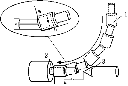
[0029] S2: Obtain the maximum length of the workpiece to be processed and the minimum distance between the loading and unloading interference space in the CNC machine tool through measurement, as well as the matching margin between the inner diameter or outer diameter of the workpiece to be processed and the loosened or clamped state of the chuck of the CNC machine tool, Calculate the feeding angle that can allow loading and u...


PUM


Abstract

The invention provides a numerical control machine tool flexible loading and unloading method adopting a truss robot, and belongs to the technical field of metal part turning. The method comprises thefollowing steps: firstly, workpieces to be machined can realize manual loading and unloading through a certain angle; then, a feeding angle capable of allowing loading and unloading is calculated; and an obstacle avoiding path of clamped workpieces in a numerical control machine tool is planned in a truss robot control unit. According to a needed normal machine tool loading and unloading flow, loading and unloading actions of the truss robot in limited operation space in the numerical control machine tool are simulated and monitored through one step, and meanwhile, the chuck loosening and tightening actions of the numerical control machine tool are matched; and after one step is repeatedly exerted correctly, the full-automatic work flow of a truss robot loading and unloading system can berecovered, so that the loading and unloading space limiting problem in the numerical control machine tool is effectively solved.

Description

technical field [0001] The invention relates to the technical field of turning of metal parts, in particular to a flexible loading and unloading method of a numerically controlled machine tool using a truss robot. Background technique [0002] The reasonable use of CNC machine tool loading and unloading robots can replace operators to complete repetitive, boring and potentially dangerous work, which can greatly reduce the labor intensity of personnel, improve processing rhythm and production efficiency, and reduce costs and increase efficiency for enterprise production. Industrial robots that can be used for loading and unloading operations on CNC machine tools are mainly divided into two types: joint robots and truss robots. Among them, joint robots generally adopt five to six degrees of freedom, with flexible operation and good equipment adaptability. They mostly use precision reducer transmission, high repeat positioning accuracy, and high machining accuracy of parts. How...

Claims


Application Information

Patent Timeline
Patent Type & Authority Patents(China)
IPC IPC(8): B23B15/00
Inventor 张勇军张辉肖雄郭强胡水平
Owner UNIV OF SCI & TECH BEIJING
Learn More