Casing for borehole gas drainage

A gas extraction and casing technology, applied in drilling pipe, casing, gas discharge and other directions, can solve the problem that the continuity and maximization of gas extraction cannot be achieved, work efficiency and safety are reduced, and the extraction volume of a single hole is reduced. and other problems to achieve the effect of improving work efficiency and safety, reducing sealing time, and ensuring maximum effect.

Active Publication Date: 2020-03-10
HUAINAN MINING IND GRP
View PDF7 Cites 0 Cited by
  • Summary
  • Abstract
  • Description
  • Claims
  • Application Information

AI Technical Summary

Problems solved by technology

In the prior art, the casing used for drilling gas drainage uses core pipes throughout the whole process, and the casing is lowered by a drilling rig, and protected with a palm rope or a pipe clip. When using this casing, when the working face pushes through the drill After the hole, the broken rock in the hole will enter the casing, forming a blockage phenomenon, resulting in a large amount of pressure relief gas without drainage channels, and the single hole drainage rate decreases rapidly, which cannot realize the continuity and maximum of gas drainage, reducing the Work efficiency and safety, increase the sealing time, seriously affect the drilling progress

Method used


Image

  • Casing for borehole gas drainage
  • Casing for borehole gas drainage
  • Casing for borehole gas drainage

Examples


Embodiment 1

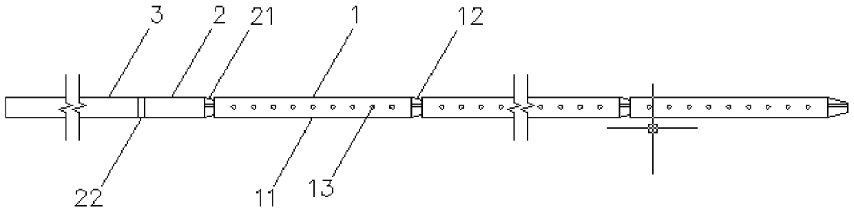
[0021] like Figure 1-4 As shown, the casing used for drilling gas drainage includes an insertion pipe 1 , a connecting variable head 2 , and a core pipe 3 .

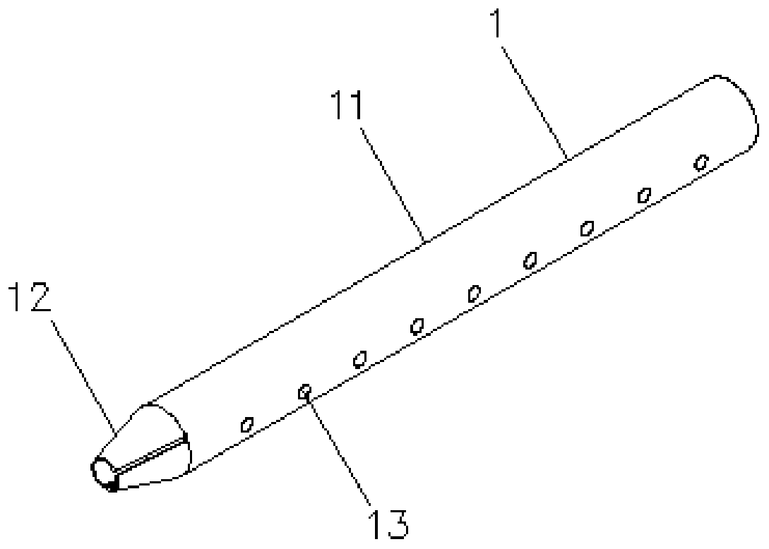
[0022] The plug-in pipe 1 includes a pipe body 11 and a plug-in joint 12, and the pipe body 11 is provided with a plurality of flow holes 13.

[0023] The pipe body 11 and the plug joint 12 are integrally structured, and one end of the plug joint 12 is connected to one end of the pipe body 11. The length of the pipe body 11 is 1200 mm, and the length of the plug joint 12 is 80 mm.

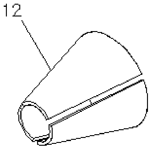
[0024] The tube body 11 is a round tube; the plug-in joint 12 is in the shape of a round platform, the bottom surface of the round platform is connected to one end of the tube body 11 and its diameter is equal to the diameter of the tube body 11, and the diameter of the top surface of the round platform is smaller than the diameter of the bottom surface; The angle between the extension line and the extension line of the central axis is 20°....

Embodiment 2

[0035] The difference between this embodiment and Embodiment 1 is:

[0036] The length of the pipe body 11 is 1500mm, and the length of the plug joint 12 is 120mm.

[0037] The angle between the extension line of the plug connector 12 round table busbar and the extension line of the central axis is 30°

[0038] The interval between adjacent flow holes 13 is 110 mm, and the diameter of the flow holes 13 is 22 mm.


PUM


Abstract

The invention discloses a casing for drilling gas extraction, and relates to the field of coal mine underground drilling. The casing includes inserting pipes, each inserting pipe includes a pipe bodyand an inserting joint, and the pipe bodies are provided with a plurality of flow holes; the pipe bodies and the inserting joints are of an integral structure, one ends of the inserting joints are connected with one ends of the pipe bodies, a plurality of gaps are formed in the pipe walls of the inserting joints, the multiple inserting joints are connected end to end, and the inserting joint of the latter inserting pipe is inserted into the end of the pipe body of the former inserting pipe; and the front half part of each inserting joint is inserted into the corresponding pipe body, the secondhalf part of the inserting joint is exposed, and the gap of the inserting joint extends to the second half part and is exposed with the second half part. The casing for drilling gas extraction has the advantages that the phenomenon of casing blockage during gas extraction is avoided, and a gas extraction passage is maintained to be smooth.

Description

technical field [0001] The invention relates to the field of underground drilling in coal mines, in particular to a casing used for drilling gas drainage. Background technique [0002] After the drilling of the roof of the coal mine working face is completed, the casing needs to be installed to protect the hole, and the gas drainage is carried out through the casing. In the prior art, the casing used for drilling gas drainage uses core pipes throughout the whole process. The casing is lowered by a drilling rig and protected with a palm rope or pipe clip. When using this casing, when the working face pushes through the drill After the hole is drilled, the broken rock in the hole will enter the casing, forming a blockage phenomenon, resulting in a large amount of pressure relief gas without drainage channels, and the single-hole drainage rate decreases rapidly, making it impossible to realize the continuity and maximum of gas drainage, reducing the Work efficiency and safety ...

Claims


Application Information

Patent Timeline
Patent Type & Authority Patents(China)
IPC IPC(8): E21B17/08E21F7/00
Inventor 刘东生石德洲魏涛
Owner HUAINAN MINING IND GRP
Why Eureka
Try Eureka