A charging and discharging control method for energy storage units in a distributed energy storage DC microgrid
A technology of distributed energy storage and DC microgrid, which is applied in the direction of parallel operation of DC power supplies, electrical components, battery circuit devices, etc., can solve the problem of short life of the energy storage unit of the state of charge value, and achieve the effect of fast and accurate balance
- Summary
- Abstract
- Description
- Claims
- Application Information
AI Technical Summary
Problems solved by technology
Method used
Image
Examples
Embodiment 1
[0044] A charging and discharging control method for an energy storage unit in a distributed energy storage DC microgrid. In the discharging phase, the controller corresponding to the pth energy storage unit controls its discharge, and the controller corresponding to the qth energy storage unit controls its discharge. , and when SOC p >SOC q When , the discharge current controlled by the controller corresponding to the pth energy storage unit is greater than the discharge current controlled by the controller corresponding to the qth energy storage unit; in the charging stage, the controller corresponding to the pth energy storage unit Control its charging, the controller corresponding to the qth energy storage unit controls its charging, and when SOC p >SOC q , the charging current controlled by the controller corresponding to the pth energy storage unit is greater than the charging current controlled by the controller corresponding to the qth energy storage unit; where p an...
Embodiment 2
[0067] On the basis of embodiment one, the governing equation is: u dcj = u dcref -K j i dcj ·G j + r j i dcj , where r j Indicates the line impedance corresponding to the jth energy storage unit.
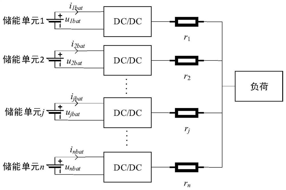
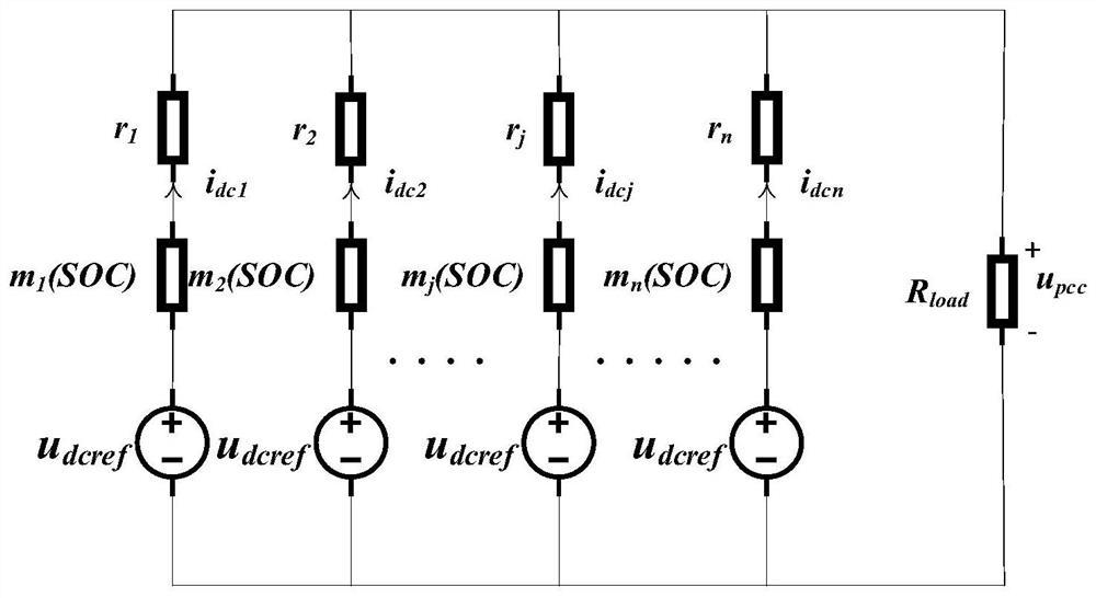
[0068] For example, figure 1 The power system in is simplified to get figure 2 ,Such as figure 2 As shown, n voltages are u dcref The power supply passes through the resistance m j (SOC) and r j The impedances are connected in parallel with each other, while giving an impedance of R load The resistor power supply, u pcc is the common point voltage, i dcj For the jth energy storage unit, the resistance is m j The output current output by the resistance of (SOC) can be obtained from the circuit relationship:
[0069]
[0070] The subscript j represents the relevant variable of the jth energy storage unit, such as i dcj Represents the output current of the jth energy storage unit, R s is the parallel impedance, and n represents the total number of energy storage...
Embodiment 3
[0092] A charging and discharging control system for energy storage units in a distributed energy storage DC microgrid, including: controllers corresponding to all energy storage units in the distributed energy storage DC microgrid; The controller controls its discharge, and the controller corresponding to the qth energy storage unit controls its discharge, and when the SOC p >SOC q , the discharge current controlled by the controller corresponding to the pth energy storage unit is greater than the discharge current controlled by the controller corresponding to the qth energy storage unit; in the charging stage, the pth energy storage unit corresponds to The controller controls its charging, and the controller corresponding to the qth energy storage unit controls its charging, and when the SOC p >SOC q , the charging current controlled by the controller corresponding to the pth energy storage unit is greater than the charging current controlled by the controller correspondin...
PUM
 Abstract
Description
Claims
Application Information
 - R&D
- Intellectual Property
- Life Sciences
- Materials
- Tech Scout
- Unparalleled Data Quality
- Higher Quality Content
- 60% Fewer Hallucinations
Browse by: Latest US Patents, China's latest patents, Technical Efficacy Thesaurus, Application Domain, Technology Topic, Popular Technical Reports.
© 2025 PatSnap. All rights reserved.Legal|Privacy policy|Modern Slavery Act Transparency Statement|Sitemap|About US| Contact US: help@patsnap.com


