Sheet metal part die-free machining method

A metal sheet metal part and processing method technology, applied in the field of metal sheet metal parts manufacturing, can solve the problems of uneven thickness of sheet metal, cracked parts, large gap, etc., to achieve uniform wall thickness distribution, improved sheet metal distribution, Thick and even effect

Active Publication Date: 2019-06-21
NANJING UNIV OF AERONAUTICS & ASTRONAUTICS
View PDF7 Cites 2 Cited by
  • Summary
  • Abstract
  • Description
  • Claims
  • Application Information

AI Technical Summary

Problems solved by technology

[0004] For the existing sheet metal incremental forming technology, the wall thickness of the sheet metal is subject to the constraints of the sinusoidal law during the processing (ie In the formula, t 0 is the thickness of the sheet before forming, t is the thickness of the sheet after forming, is the angle between the forming surface of the sheet metal and the vertical direction, that is, the forming wall angle), if the forming angle is large, the wall thickness will be seriously thinned, and even the part will be broken
Generally, the multi-pass progressive forming process can increase the forming angle of the sheet and improve the forming limit, but it is still difficult to solve the situation of uneven thickness and large gaps in the processing process.

Method used


Image

  • Sheet metal part die-free machining method
  • Sheet metal part die-free machining method
  • Sheet metal part die-free machining method

Examples


Embodiment

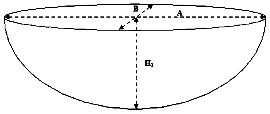
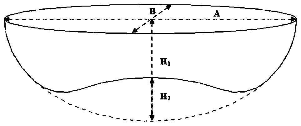
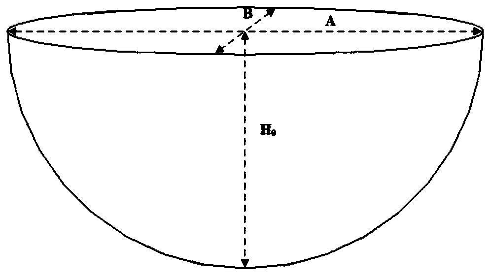
[0025] In this embodiment, the workpiece to be formed is a semi-ellipsoid, the length of the opening is represented by A, the width is represented by B, and the height is represented by H.

[0026] The dieless processing method for metal sheet metal parts of the present embodiment comprises the following steps:

[0027] Step 1. Fix the four boundaries of the rectangular sheet metal on the forming machine tool through clamps. In order to facilitate processing and forming, a layer of lubricating oil can be applied to the rectangular sheet metal.

[0028] Step 2. Build a figure 1 The first intermediate configuration of the shown semi-ellipsoid shape, the two equatorial radii (major axis and minor axis) of the semi-ellipsoid are respectively half of the length and width of the sheet material, and the surface area of ​​the first intermediate configuration is 60-80% of the surface area of ​​the final metal sheet metal part, preferably about 70% in this embodiment.

[0029] The for...


PUM


Abstract

The invention relates to a sheet metal part die-free machining method. The sheet metal part die-free machining method comprises the following steps that firstly, four boundaries of a rectangular metalplate material are fixed to a forming machine tool through clamps; secondly, a half-ellipsoid-shaped die is formed as a first intermediate structure, the surface area of the first intermediate structure accounts for 60-80% of the surface area of the finally formed part, and the first intermediate structure is formed in the first pass; thirdly, a reversely raised swell is established upwards fromthe center of the lower side of the first intermediate structure and used as a second intermediate structure, the area of the raised swell accounts for 30-40% of the surface area of the first intermediate structure, and a lower forming tool is adopted to form the second intermediate structure along a preset second formation path in the second pass; and fourthly, the second intermediate structure is machined to be in the shape of the finally formed part in the third pass. The sheet metal part die-free machining method does not need a dedicated mold, the machining period is short, and a large-wall angle or straight-angle piece, complicated-structure pieces and other parts difficult to machine can be formed.

Description

technical field [0001] The invention relates to a moldless processing method for metal sheet metal parts, which belongs to the technical field of metal sheet metal part manufacturing. Background technique [0002] Metal sheet metal processing is widely used in industrial fields such as automobiles, ships, aerospace, military weapons, and daily hardware. It has the characteristics of high efficiency, low cost, and mass production. [0003] In recent years, with the rapid development of science and technology and the national economy, the demand for industrial products tends to be individualized, and the cycle of design updates is shortened, making traditional sheet metal forming such as stamping forming unable to meet the needs of many actual production and processing. In order to meet the flexible market demand, many dieless sheet metal forming technologies have emerged. Among them, CNC progressive forming technology is a new flexible manufacturing forming technology emergi...

Claims


Application Information

Patent Timeline
Patent Type & Authority Applications(China)
IPC IPC(8): B21D31/00
Inventor 金霞胡俊聪蔡顺陈樱利鲍益东
Owner NANJING UNIV OF AERONAUTICS & ASTRONAUTICS
Why Eureka
Try Eureka