Method and device for vertical lifting of muck

A muck and vertical technology, applied in the field of muck vertical lifting methods and devices, can solve the problems of discontinuous excavation, inability to realize muck crushing and filtering classification, and inability to effectively control the impact force of muck, etc. , to achieve the effect of low transportation cost, guaranteed excavation speed and continuous work

Inactive Publication Date: 2020-08-28
北京住总集团有限责任公司
View PDF10 Cites 0 Cited by
  • Summary
  • Abstract
  • Description
  • Claims
  • Application Information

AI Technical Summary

Problems solved by technology

However, when the length of the above-mentioned conveyor needs to be increased, it is necessary to shut down its upstream, such as an excavator, resulting in discontinuity of the entire excavation work.
Moreover, the conveyor cannot effectively control the impact of the muck, nor can it realize the crushing and filtering of the muck.

Method used


Image

  • Method and device for vertical lifting of muck
  • Method and device for vertical lifting of muck
  • Method and device for vertical lifting of muck

Examples


Embodiment 1

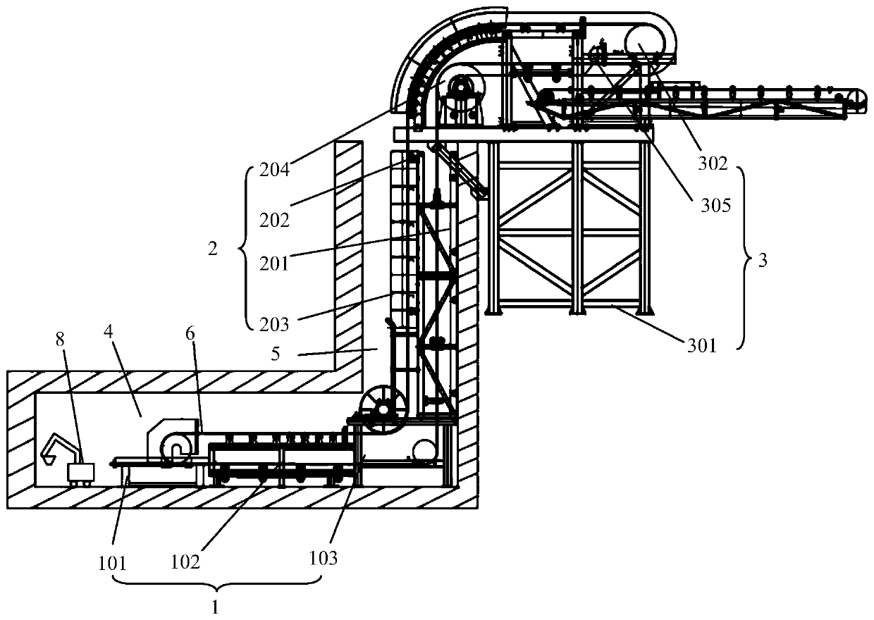
[0053] Such as figure 1 As shown, the present invention provides a muck vertical lifting device, which can be used in the construction of subway underground tunnels or deep foundation pits. The muck vertical lifting device at least includes a first horizontal conveying part 1 , a vertical lifting part 2 and a second horizontal conveying part 3 . The first horizontal conveying part 1 is arranged at the bottom of the tunnel 4 to transfer, for example, muck excavated by an excavator to the bottom of the shaft. The vertical lifting part 2 is arranged on the side wall of the shaft 5, and is used for vertically lifting the muck at the bottom of the shaft, and then can lift the muck to the surface along the shaft 5. The second horizontal conveying part 3 is arranged on the ground surface, and it is used for transferring the dregs lifted by the vertical lifting part 2 to the muck storage yard, for example. The vertical lifting part 2 can transport the muck from the first horizontal ...

Embodiment 2

[0059] This embodiment is a further improvement on Embodiment 1, and repeated content will not be repeated here.

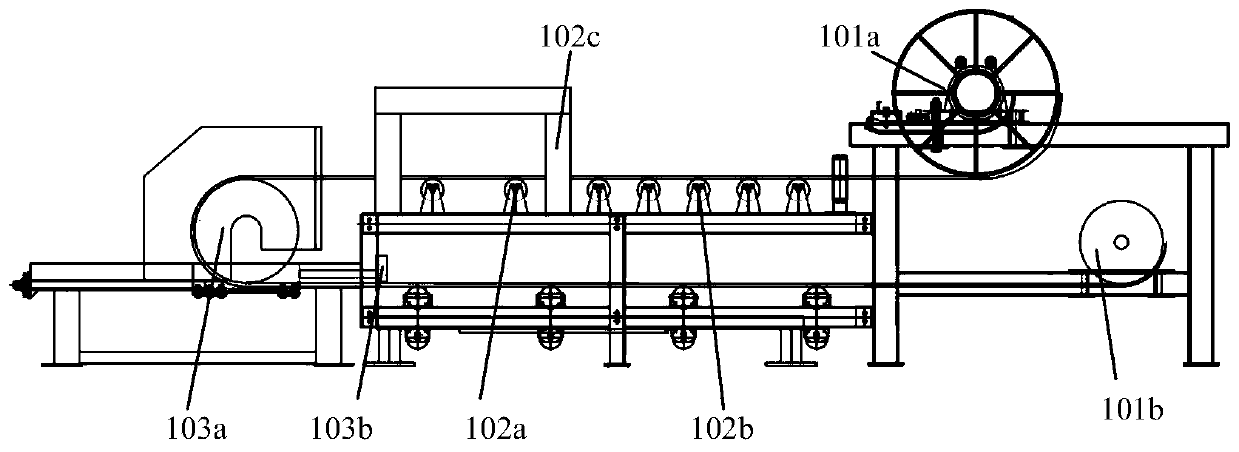
[0060] preferred, such as figure 2 As shown, the second support 102 is also provided with several parallel rollers 102b and material guide grooves 102c. The first horizontal conveying part plays the role of conveying materials through the joint rotation of the parallel idler roller 102b and the buffer idler roller 102a. Both the parallel idler roller and the buffer idler roller are arranged on the second support 102 in a manner parallel to each other. The material guide trough 102c and the buffer roller 102a are used as a pair. That is, the material guide groove 102c is arranged above the buffer idler roller 102a. The material guide trough 102c is used to receive, for example, muck excavated by an excavator, and then pour the muck onto the belt 6 on the buffer idler roller 102a. The first muck and / or the second muck can be transported through the buffer idler...

Embodiment 3

[0067] This embodiment is a further improvement on the foregoing embodiments, and repeated content will not be repeated here.

[0068] preferred, such as Figure 6 As shown, the first horizontal conveying part 1 is arranged at the intersection of the tunnel 4 and the shaft 5 . The muck vertical lifting device further includes an extended conveying part 7 composed of a first conveying unit 701 , a buffer unit 702 and a second conveying unit 703 . The extension conveying part 7 is arranged in the tunnel 4, and as the excavation continues, the length of the tunnel 4 will continue to increase. Continuous transfer.

[0069] Preferably, the first conveying unit 701 and the second conveying unit 703 may be belt conveyors. Along the extending direction of the tunnel 4, a first conveying unit 701, a buffer unit 702 and a third conveying unit 703 are sequentially arranged from inside to outside. The first conveying unit 701 is close to the excavation face of the tunnel 4 , so that t...


PUM


Abstract

The present invention relates to a method and device for vertical lifting of muck, which at least includes a first horizontal conveying part and an excavating device arranged in a tunnel, a vertical lifting part arranged in a vertical shaft and a second horizontal conveying part arranged on the ground surface. The vertical lifting part can transfer the muck from the first horizontal conveying part to the second horizontal conveying part in the way of diverting transportation, and at least an extended conveying part configured to move toward the excavating device when the straight-line distance between the excavating device and the extending conveying part is greater than a first set threshold; The straight-line distance is smaller than the first set threshold, and muck can be temporarily stored in the extended conveying portion so that the excavating device can continue to perform excavation operations.

Description

technical field [0001] The invention belongs to the technical field of tunnel construction, and in particular relates to a method and device for vertical lifting of dregs. Background technique [0002] At present, in the construction of urban subway tunnels in my country, in addition to the shield tunneling method, there are still quite a few projects that are constructed by the mining method, and the method of ballasting is a key factor affecting the efficiency of tunnel construction. If there is a vertical shaft, a small dump truck is used to transport it to the bottom of the vertical shaft for transfer, and a gantry crane is used for vertical lifting to lift the material upwards in the form of a grab bucket. In addition, when lifting vertically, there are often safety problems such as stuck chains and bucket drop phenomena in bucket elevators, grab buckets, and telescopic arms, etc. When transporting horizontally, trucks, electric tricycles and other transport equipment w...

Claims


Application Information

Patent Timeline
Patent Type & Authority Patents(China)
IPC IPC(8): B65G37/00B65G15/60B65G21/08B65G45/10B65G41/00E21F13/06E21D7/00B02C19/00B07B1/00B07B1/46
CPCB65G37/00B65G15/60B65G21/08B65G45/105B65G41/00E21F13/06E21D7/00B02C19/00B07B1/00B07B1/46B65G2201/045
Inventor 申庆梦邓彩霞鲁庆涛王青宋贺雨封小艳禹庆彬李红伟
Owner 北京住总集团有限责任公司
Why Eureka
Try Eureka