
Replaceable energy dissipation wood structure beam-column joint

A technology for column joints and wood structures, which is used in building components, building structures, and earthquake resistance. performance, reduce maintenance and repair costs, and avoid cross-grain splitting damage

Pending Publication Date: 2019-06-21
XI'AN UNIVERSITY OF ARCHITECTURE AND TECHNOLOGY
View PDF0 Cites 5 Cited by
  • Summary
  • Abstract
  • Description
  • Claims
  • Application Information

AI Technical Summary

Problems solved by technology

[0003] (1) Due to the construction deviation, there is a gap between the bolt hole wall and the bolt on the wooden beam. This gap causes the wooden beam to slide after being stressed, resulting in a low initial stiffness of the joint
[0004] (2) Due to the low tensile strength of wood cross grains, when the screw holes and pin grooves are under pressure, brittle failures such as beam end cross grain splitting often occur, and the bending resistance of wood cannot be fully exerted, which leads to the overall load bearing of the wood structure beam-column system. force drop
[0005] (3) The bearing capacity is provided by the bolt yield and the compression yield of the wood at the bolt hole, etc. After the earthquake, there is a large residual deformation, and the seismic performance is reduced
[0006] (4) Most of the nodes connected by beam-column connectors are hidden inside the beams, and there are problems of difficulty in maintenance

Method used


Image

  • Replaceable energy dissipation wood structure beam-column joint
  • Replaceable energy dissipation wood structure beam-column joint
  • Replaceable energy dissipation wood structure beam-column joint

Examples


Embodiment Construction

[0037] The implementation of the present invention will be described in detail below in conjunction with the drawings and examples.

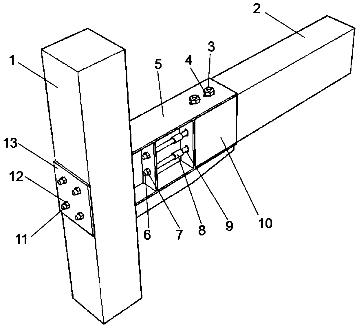
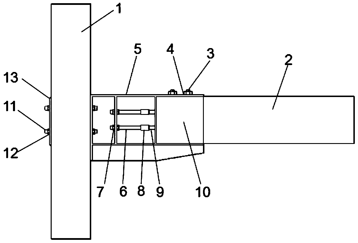
[0038] Such as figure 1 , figure 2 , image 3 with Figure 4 As shown, a replaceable energy-consuming wooden beam-column joint mainly includes beam-column connector 5, steel plate frame 10, planting reinforcement 9 and shape memory alloy screw 6, and the material of wooden beam 2 and wooden column 1 is log , sawn timber, glued or laminated veneer lumber or other engineered wood. in:

[0039] The beam-column connector 5 is located between the connection ends of the wooden column 1 and the wooden beam 2, refer to Figure 5 , which includes an I-beam, including an I-beam, and a number of vertical steel plates perpendicular to the web are welded between the upper and lower wing plates of the I-beam.

[0040] In order to further facilitate the connection, the end faces of the I-beams are closed by vertical steel plates perpendicular to the web...


PUM


Abstract

A replaceable energy dissipation wood structure beam-column joint comprises a beam column connecting piece, a steel plate frame, a plurality of embedded steel bars and a plurality of shape memory alloy screws. The beam column connecting piece is arranged on the inner side face of a wood column and located between the wood column and the connecting end of a wood beam. The steel plate frame is arranged at the end of the wood beam and attached to the upper face, the lower face, the front face and the rear face of the end face of the wood beam; the embedded steel bars are respectively embedded inhole channels or groove channels in the end surface of the wood beam through adhesive; and the shape memory alloy screws are positioned between the embedded steel bars and the beam column connecting piece. According to the invention, the pre-tightening force of high-strength bolts are adjusted, the hyperelastic performance of the shape memory alloy screws is utilized, the pre-strain, number and size of the shape memory alloy screws are adjusted, the initial rigidity and self-recovery capacity of joints are improved, it is guaranteed that the shape memory alloy screws are subjected to yield damage before beam column components, so that the maintenance and repair costs of the wood structure are greatly reduced.

Description

technical field [0001] The invention belongs to the technical field of civil engineering, in particular to a replaceable energy-consuming wooden structure beam-column joint. Background technique [0002] At present, in the beam-column structural system of wood structure, most of them adopt the joint form of bolt connection. The common form is the bolted connection of wood members. This joint form mainly uses the bending resistance of the bolts and the local pressure of the wood at the bolts to provide bearing capacity. There are several problems with this node form: [0003] (1) Due to the construction deviation, there is a gap between the bolt hole wall and the bolt on the wooden beam. This gap causes the wooden beam to slide after being stressed, resulting in a low initial stiffness of the joint. [0004] (2) Due to the low tensile strength of the transverse grain of the wood, when the screw hole pin groove is under pressure, brittle failures such as splitting of the tra...

Claims


Application Information

Patent Timeline
IPC IPC(8): E04B1/26E04B1/58E04B1/98E04H9/02
Inventor 谢启芳李胜英赵佳程远洋王凡
Owner XI'AN UNIVERSITY OF ARCHITECTURE AND TECHNOLOGY
Learn More