Limiting shaft on floor spring and manufacturing method thereof

A production method and a technology of a limit shaft, which are applied in the field of floor spring accessories, can solve problems such as high processing quality, low pass rate, and difficult processing, and achieve the effects of improving production efficiency, increasing pass rate, and easy size control

Pending Publication Date: 2019-06-21
台州市计量设备技术校准中心 +1
View PDF6 Cites 2 Cited by
  • Summary
  • Abstract
  • Description
  • Claims
  • Application Information

AI Technical Summary

Problems solved by technology

However, this integral forging method has very high requirements for processing quality, and it is also very difficult to process, especially a suitable distance between the main cam and the auxiliary cam is required and the distance is relatively small, and the central axis The shapes of both ends and the shape of the main cam and the auxiliary cam are quite special, and there are very high requirements for the selection and use of processing tools. Once a deviation occurs in the processing of a certain position, the entire product will be scrapped, so there is still a qualified low rate problem

Method used


Image

  • Limiting shaft on floor spring and manufacturing method thereof
  • Limiting shaft on floor spring and manufacturing method thereof
  • Limiting shaft on floor spring and manufacturing method thereof

Examples


Embodiment Construction

[0040] The following are specific embodiments of the present invention and in conjunction with the accompanying drawings, the technical solutions of the present invention are further described, but the present invention is not limited to these embodiments.

[0041] A method for manufacturing a limit shaft on a floor spring, the method comprising the following steps:

[0042] a. Cutting: cut the next bar blank on a metal bar, and the length of the bar blank is cut according to the design length of the limit shaft;

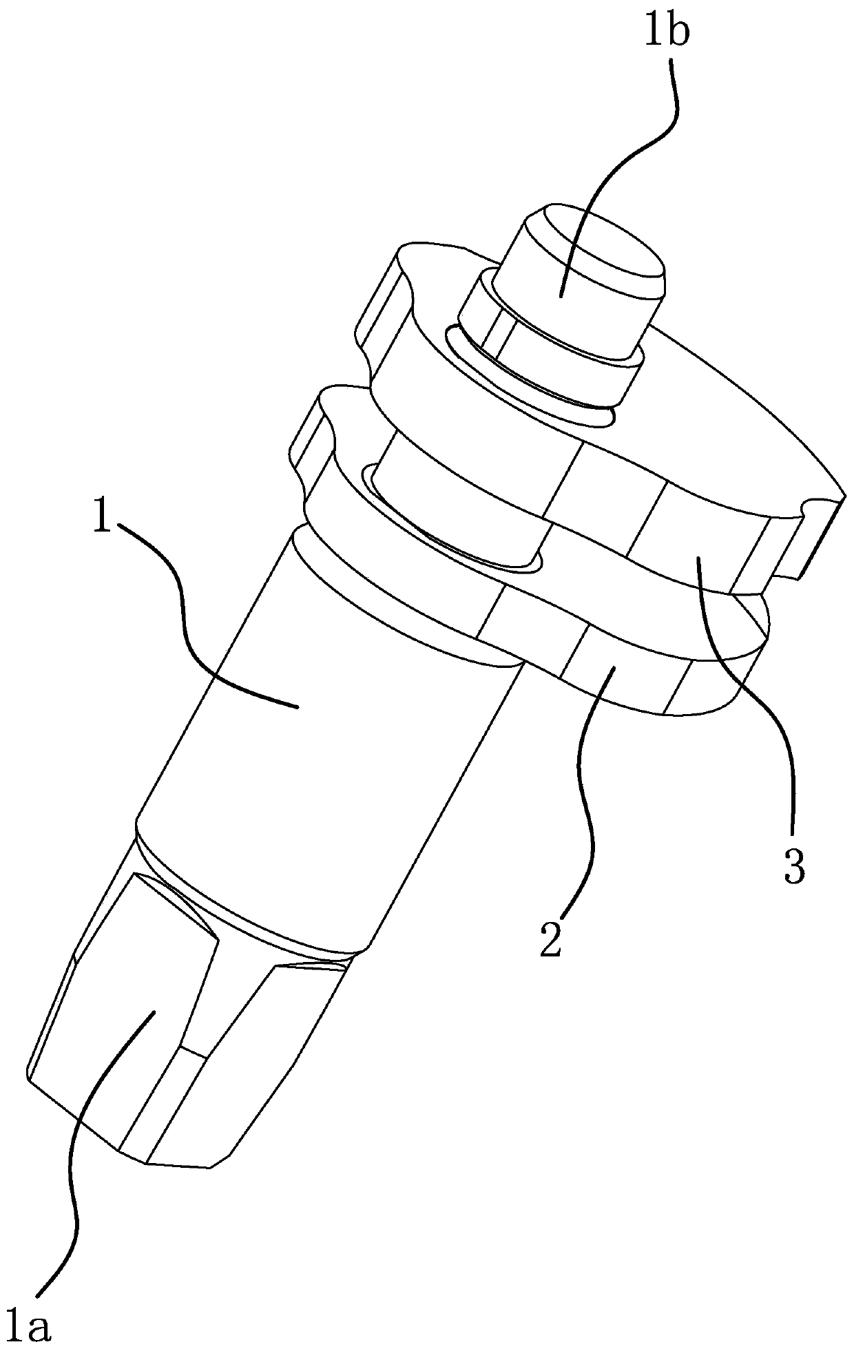
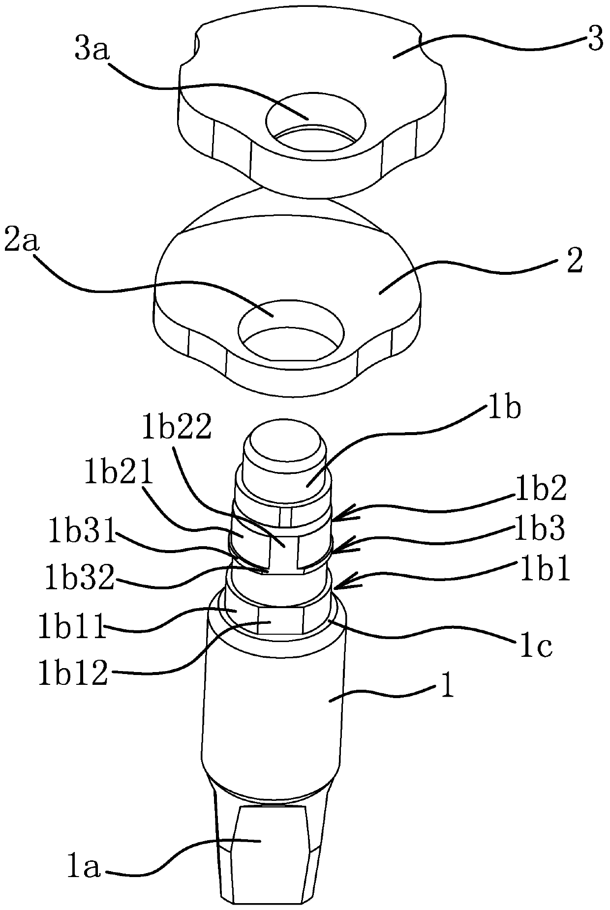
[0043] b. Shaft body 1 forming: Place the bar blank obtained in step a on a CNC machine tool for machining, so that the bar blank forms a shaft body 1 with a coupling head 1a at one end and a positioning head 1b at the other end, and the coupling head 1a The shape of the hole is the same as that of the hole at the bottom of the door, and at the same time, the convex ring one 1b1 and the convex ring two 1b2 are processed axially on the positioning head 1b;

[0044] ...


PUM


Abstract

The invention provides a limiting shaft on a floor spring and a manufacturing method thereof, belongs to the technical field of floor spring accessories, and solves the problems that an existing limiting shaft is difficult to machine and low in percent of pass. The limiting shaft on the floor spring comprises a shaft body, a first cam and a second cam. a coupling head is arranged at one end of theshaft body; a positioning head is arranged at the other end of the shaft body; a first convex ring and a second convex ring are arranged on the outer side of the positioning head in the axial direction; the outer peripheral surface of the first convex ring comprises a first arc surface and a first straight surface connected between the two ends of the first arc surface; a first matching hole which is the same as the first convex ring in shape is formed in the first cam; the first cam is fixed to the first convex ring through the first matching hole, the outer circumferential face of the second convex ring comprises a second arc surface and a second straight face connected between the two ends of the second arc surface, the second cam is provided with a second matching hole which is the same as the second convex ring in shape, the second cam is fixed to the second convex ring through the second matching hole, and the first straight face and the second straight face are located on the same plane. The limiting shaft on the floor spring has the advantages of high qualification rate, convenience in processing, high positioning precision and the like.

Description

technical field [0001] The invention belongs to the technical field of floor spring accessories, and relates to a limit shaft on a floor spring and a manufacturing method thereof. Background technique [0002] The ground spring is a hydraulic door closer. Its structure is, for example, a door force adjustable multi-stage positioning ground spring disclosed in the application number 201410660425.5. It includes a valve body and a central shaft. The valve body is provided with a valve body cavity and a movable The two ends of the valve body cavity are respectively provided with a piston and a back cover, and a spring is connected between the piston and the back cover. The upper pull-up piece, the main cam, the auxiliary cam and the pull-down piece are arranged in sequence in the movable chamber from top to bottom. There are guide grooves on both the pull-down piece and the pull-down piece. The central axis passes through the guide grooves of the upper pull-down piece and the pu...

Claims


Application Information

Patent Timeline
Patent Type & Authority Applications(China)
IPC IPC(8): E05D7/08E05F3/04
Inventor 徐欣陈康王超邬振华李岳求
Owner 台州市计量设备技术校准中心
Why Eureka
Try Eureka