Automobile disc-type brake system

A disc brake and brake system technology, applied in the direction of brake types, brake actuators, brake components, etc., can solve the problem of limited fluid compression space, wear and tear of rust-proof and wear-resistant layers, brake pads and brakes Disk wear and other problems, to achieve the effect of improving the heat dissipation effect, enhancing the heat dissipation effect, and preventing secondary wear

Active Publication Date: 2019-06-21
HUBEI UNIV OF SCI & TECH
View PDF5 Cites 2 Cited by
  • Summary
  • Abstract
  • Description
  • Claims
  • Application Information

AI Technical Summary

Problems solved by technology

[0002] Automobile disc brakes provide braking force by clamping the two sides of the brake disc through the brake caliper. The power comes from the hydraulically driven piston. The end of the piston is equipped with a brake pad, and the piston pushes the brake pad into contact with the brake disc. To achieve friction braking, the size of the hydraulic pressure is controlled by the pedal stroke, and the brake pad needs to be replaced after a period of use. The reason is that its wear leads to the weakening of the braking force under the same pedal stroke, causing safety hazards, that is to say, the disc brake system The brake pads cannot be automatically compensated. After the brake pads are worn out, manual adjustment is required to compensate for the wear gap.
[0003] The two brake pads at both ends of the brake caliper are synchronously close to the brake disc, and the contact position between the two is located on the opposite side of the brake disc. The heat generated during the friction braking process is concentrated on this part, causing the part to heat up. Concentration, while affecting the braking effect, the wear of the brake pads and brake discs will be intensified, which is not conducive to the service life and durability of the wearing parts in the braking system
[0004] The above-mentioned factors are more than one of the factors that cause the high temperature of the brake pads and brake discs. The cushioning when the brake pads are close to the brake discs and in contact with them all depends on hydraulic oil, and its cushioning effect is very poor, basically it can be said to be none. There is a large delay in the reaction received, and the compression space of the liquid is very limited. During emergency braking, the brake pads are directly close to the brake disc, and the rigid contact causes heat collection. At the same time, the inching braking effect depends on the ABS pump and the braking system. The control program of the dynamic cylinder makes the structure of the brake system complex, and the reliability of the electronic control components directly affects the reliability of the brake system. Moreover, there is a delay in the brake pads being in contact with the brake disc through the ABS pump, which has a great impact on the braking system. The wear of the sheet is greater
[0005] In the existing disc brake system, the wear position of the brake disc is single (annular area in contact with the brake pad), and the wear track is single (worn clockwise or counterclockwise along the annular area of ​​contact). The disk basically adopts a slot-type ventilation structure or a hole-type ventilation structure, and its surface is also plated or coated or heat-treated with an anti-rust and wear-resistant layer. The single wear position and wear track will cause the rust-proof and wear-resistant layer to be quickly destroyed Wear out, causing problems such as rust and poor braking effect
What I want to talk about here is the problem of insufficient utilization of the brake disc in the existing braking system. Due to the influence of the installation position of the brake caliper and its related components, the brake pad can only occupy a small area of ​​the brake disc. The position is in an idle and unusable position, so that the frictional contact area during braking is small, the braking effect is poor, the wear position is single, and the surfaces on both sides of the brake disc cannot be fully utilized

Method used


Image

  • Automobile disc-type brake system
  • Automobile disc-type brake system
  • Automobile disc-type brake system

Examples


Embodiment Construction

[0025] The following are specific embodiments of the present invention in conjunction with the accompanying drawings to further describe the technical solutions of the present invention, but the present invention is not limited to these embodiments.

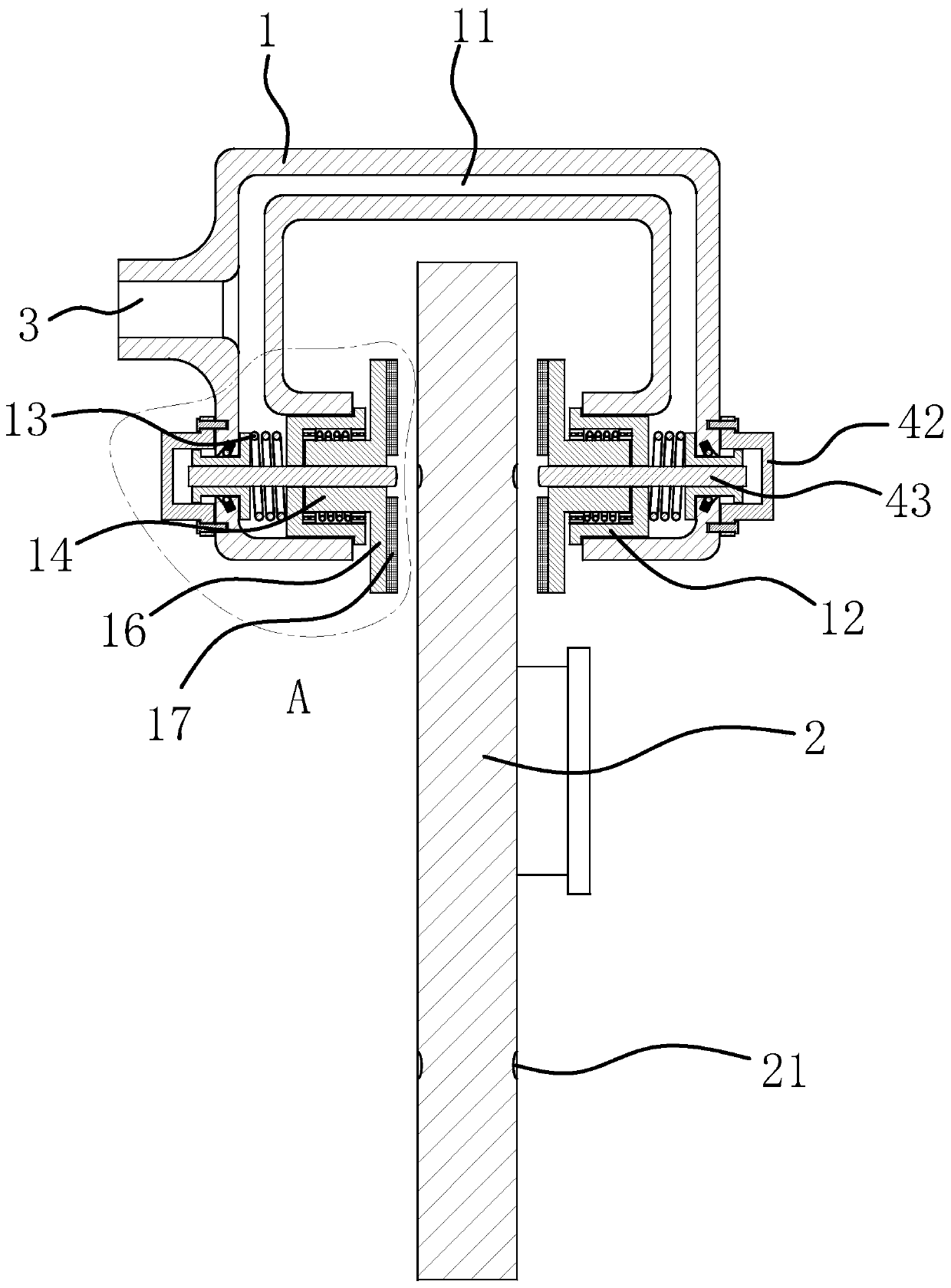
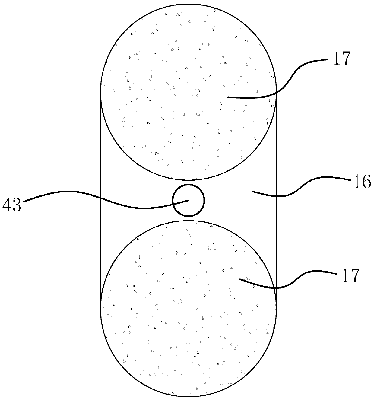
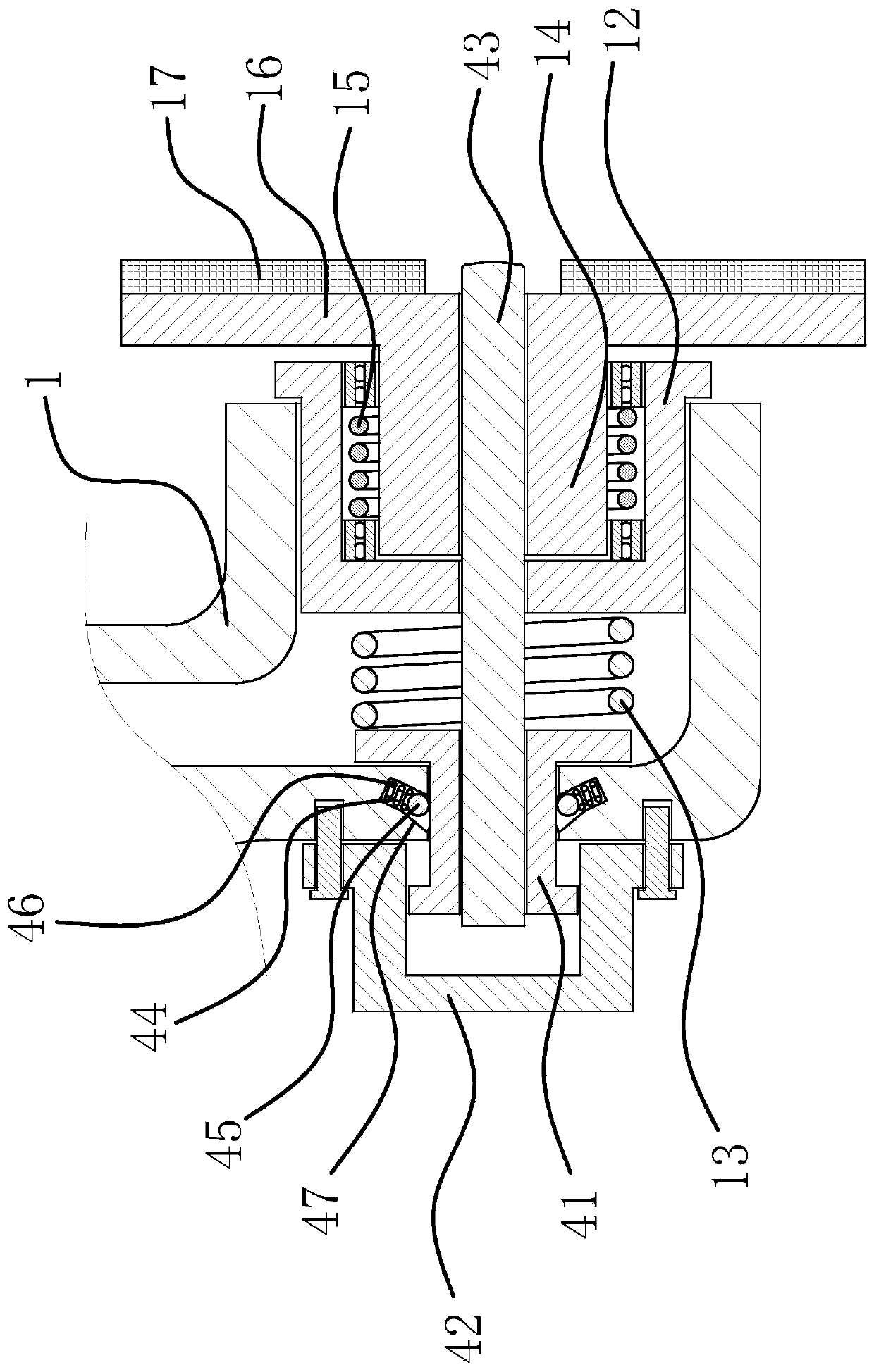
[0026] Such as figure 1 , figure 2 with image 3 As shown, the disc brake system includes a brake caliper card 1 and a brake disc 2. The brake caliper card 1 has a hydraulic channel 11, and the two ends of the brake caliper card 1 respectively have a The brake end is provided with a valve hole communicating with the hydraulic channel 11 and perpendicular to the brake disc 2. A brake piston 12 is slidably connected in the valve hole. The outer end of the brake piston 12 is between the inner wall of the hydraulic channel 11. A return spring 13 is connected between the brake piston 12 and a guide hole is opened at the inner end of the brake piston 12. A mounting shaft 14 is inserted into the guide hole. The outer end of the mounting s...


PUM


Abstract

The invention provides an automobile disc-type brake system, and belongs to the technical field of automobile parts. Brake ends located at the two sides of a brake disc are arranged at the two ends ofa brake caliper clamp separately; each brake end is provided with a valve hole communicating with a hydraulic channel and vertical to the brake disc; a brake piston is slidably connected into each valve hole; a return spring is connected between the outer end of each brake piston and the inner wall of the hydraulic channel; a guide hole is formed in the inner end of each brake piston; a torsionalspring sleeving an installation shaft is arranged between two bearings; the two ends of the torsional spring are connected with the inner walls of the guide holes and the outer wall of the installation shaft separately; a waist-shaped installation plate parallel to the brake disc is arranged at the other end of the installation shaft; and two circular brake sheets are fixedly arranged on the inner side surface of the installation plate. In a return state of the brake pistons, the connection line between the two brake sheets on the same installation plate forms an inclination angle of less than 90 degrees with the radial line of the brake disc. The automobile disc-type brake system has the advantages of being capable of providing pre-brake before brake, and the like.

Description

Technical field [0001] The invention belongs to the technical field of automobile parts and relates to an automobile disc brake system. Background technique [0002] Automobile disc brakes use brake calipers to clamp both sides of the brake disc to provide braking force. The power comes from a hydraulically driven piston. The end of the piston is equipped with a brake pad. The piston pushes the brake pad into contact with the brake disc. To achieve friction braking, the hydraulic pressure is controlled by the pedal stroke. The brake pads need to be replaced after a period of use. The reason is that its wear leads to the weakening of the braking force under the same pedal stroke, causing safety hazards, that is, the disc brake system The brake pads cannot be automatically compensated. After the brake pads are worn, manual adjustment is needed to compensate for the wear gap. [0003] The two brake pads at both ends of the brake caliper card are synchronously close to the brake disc,...

Claims


Application Information

Patent Timeline
Patent Type & Authority Applications(China)
IPC IPC(8): F16D65/14F16D65/72F16D65/847F16D121/04
Inventor 田凤霞
Owner HUBEI UNIV OF SCI & TECH
Why Eureka
Try Eureka