
Rotary sample stage device based on atomic force microscope

A technology of atomic force microscope and sample stage, which is applied in measuring devices, scanning probe microscopy, instruments, etc., can solve the problems of different force conditions, the inability of the initial sample stage to rotate at an accurate angle, and the error of measurement results, etc., to achieve Effects of reducing deformation differences, expanding application occasions and research scope, and adding functions

Active Publication Date: 2019-06-21
SOUTHWEST JIAOTONG UNIV
View PDF13 Cites 2 Cited by
  • Summary
  • Abstract
  • Description
  • Claims
  • Application Information

AI Technical Summary

Problems solved by technology

[0004] At present, almost all initial sample stages of atomic force microscopes cannot perform precise angular rotation
When the atomic force microscope is used to test and analyze the different crystal orientations of anisotropic crystal materials, if the piezoelectric ceramics is used to control the sample stage to move in different directions, due to the different relative positions of the different moving directions and the cantilever, the force on the needle tip and the micro-cantilever will be caused. Depending on the situation, the difference in the expansion and torsional elastic coefficients of the micro-cantilever system in different axes makes the deformation inconsistent, which will bring large errors to the measurement results

Method used


Image

  • Rotary sample stage device based on atomic force microscope
  • Rotary sample stage device based on atomic force microscope
  • Rotary sample stage device based on atomic force microscope

Examples


no. 1 example

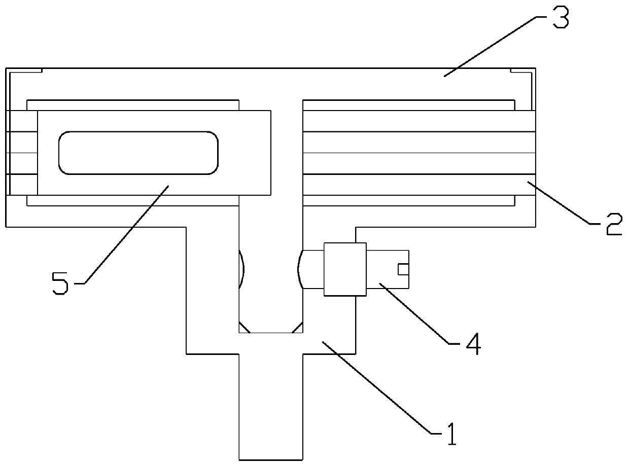
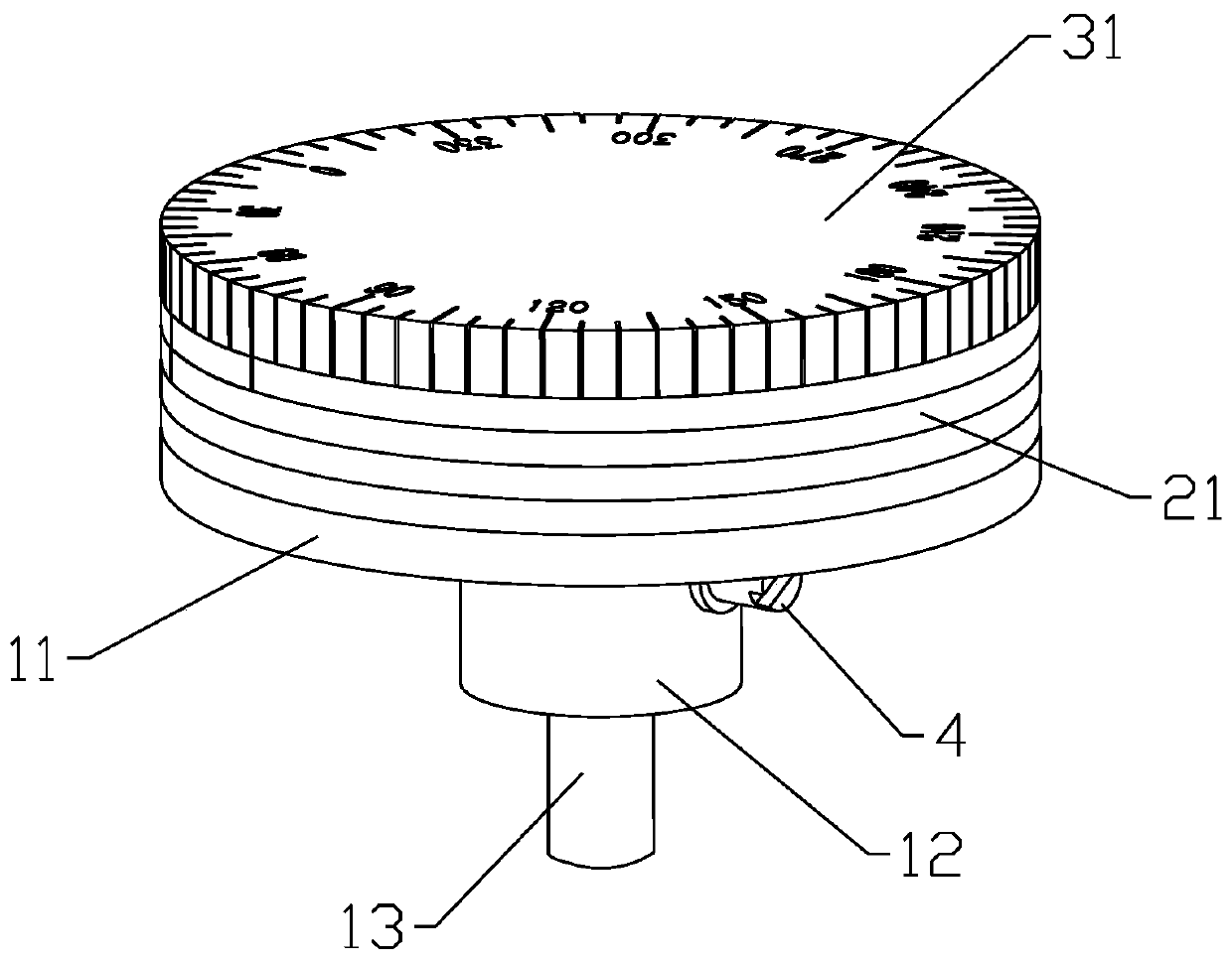
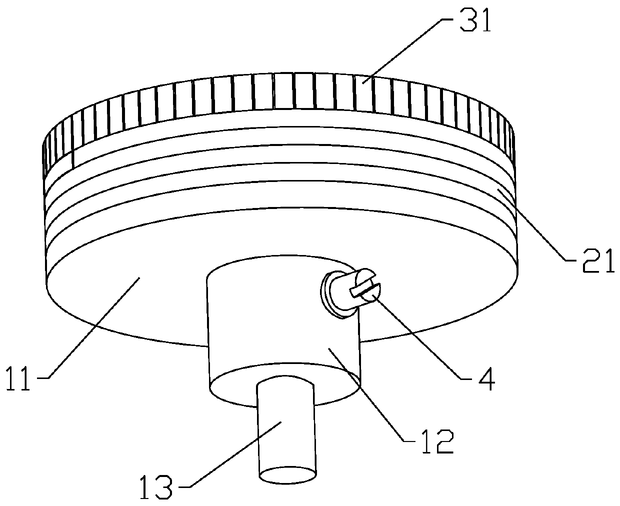
[0033] Please refer to figure 1 , figure 2 with image 3 , this embodiment provides a rotating sample stage device based on an atomic force microscope, which includes: a base 1, a thin ring body 2, a top cover 3, a pin 4 and a spring leaf 5, and the top cover 3, the thin ring body 2 and the base 1 The shapes are matched, and the top cover 3 rotates around the central axis of the three to drive the sample to rotate. It processes a plurality of thin ring bodies 2 with a uniform standard. The inner side of the thin ring body 2 is processed with a plurality of evenly distributed convex teeth 22. The thin ring bodies 2 are stacked with staggered angles in turn to form a whole, so that the protruding teeth 22 in different thin ring bodies 2 can completely divide the circumference, and the bottom surface of the whole thin ring body matches with the edge protrusion of the upper boss 11 of the base 1, and Fixedly connected by welding, the lower boss 12 of the base 1 is connected wit...


PUM


Abstract

The invention discloses a rotary sample stage device based on an atomic force microscope. The device includes a top cover, thin ring bodies, a base, a pin and a spring, wherein the base is fixed on anatomic force microscope disposing table, the thin ring bodies are fixedly connected with the base, the top cover is matched with the thin ring bodies and the base in shape, a sample is driven throughrotation of the top cover to realize free rotation, different convex teeth are sequentially dialed by the spring, accurate small-angle rotation is realized, and the auxiliary positioning function isprovided by the pin and the spring. The device is advantaged in that the device can be adaptive to the small low sample disposing space of the atomic force microscope, an extra rotation angle scale isprovided for the sample under the strict size and weight limits, the self-locking function is achieved, functions of the atomic force microscope are improved while normal operation of the atomic force microscope is not influenced, and application occasions and the research scope are expanded.

Description

technical field [0001] The invention relates to the measurement and analysis technology of anisotropic materials in the field of nanometer science and technology, and relates to a rotating sample stage device based on an atomic force microscope. Background technique [0002] The atomic force microscope contacts the surface of the sample through the needle tip fixed at the end of the micro-cantilever, and the interatomic interaction force between the needle tip and the sample causes the micro-cantilever to bend or twist, and then uses a laser sensor to measure the deformation of the cantilever. After signal processing by computer, the microscopic morphology and mechanical characteristics of the sample surface are obtained. [0003] At the same time, many crystalline materials are anisotropic, that is, along different directions of the crystal lattice, the periodicity and density of atomic arrangement are not the same, resulting in different physical and chemical properties in...

Claims


Application Information

Patent Timeline
Patent Type & Authority Applications(China)
IPC IPC(8): G01Q60/24
Inventor 陈磊马韬郭杰贡健石鹏飞钱林茂
Owner SOUTHWEST JIAOTONG UNIV
Learn More