Ferrule structure, ferrule structure with fiber, and method for manufacturing ferrule structure with fiber
A structure and ferrule technology, applied in the coupling of optical waveguide, optics, light guide, etc., can solve the problems of grinding process and other problems, and achieve the effect of omitting the grinding process and simplifying the manufacturing process
- Summary
- Abstract
- Description
- Claims
- Application Information
AI Technical Summary
Problems solved by technology
Method used
Image
Examples
no. 1 approach =
[0028] ===First Embodiment===
[0029]
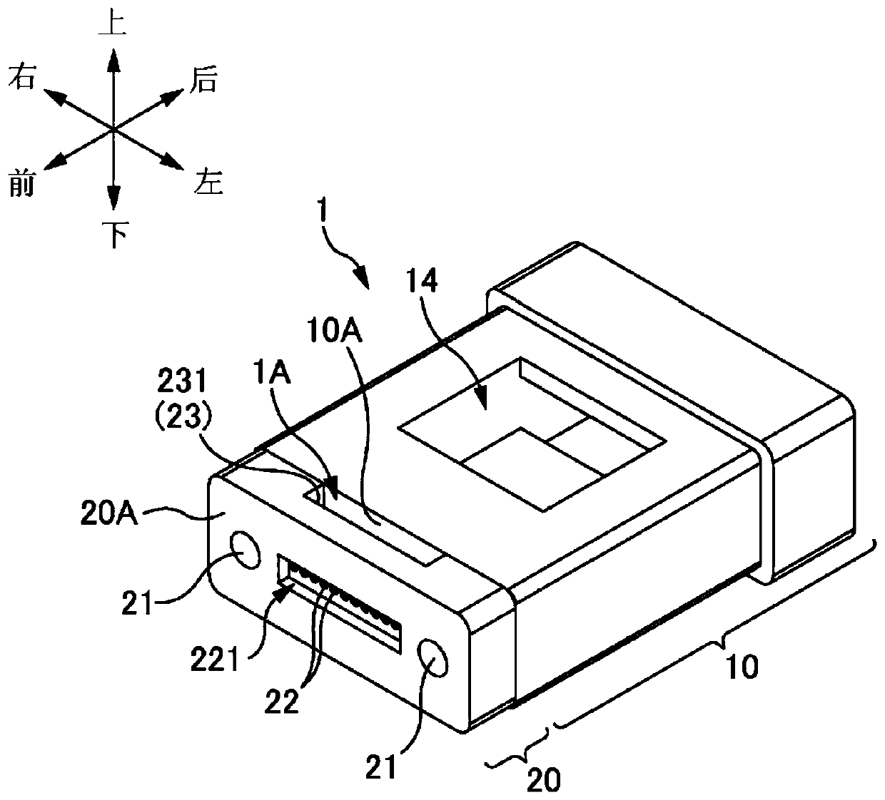
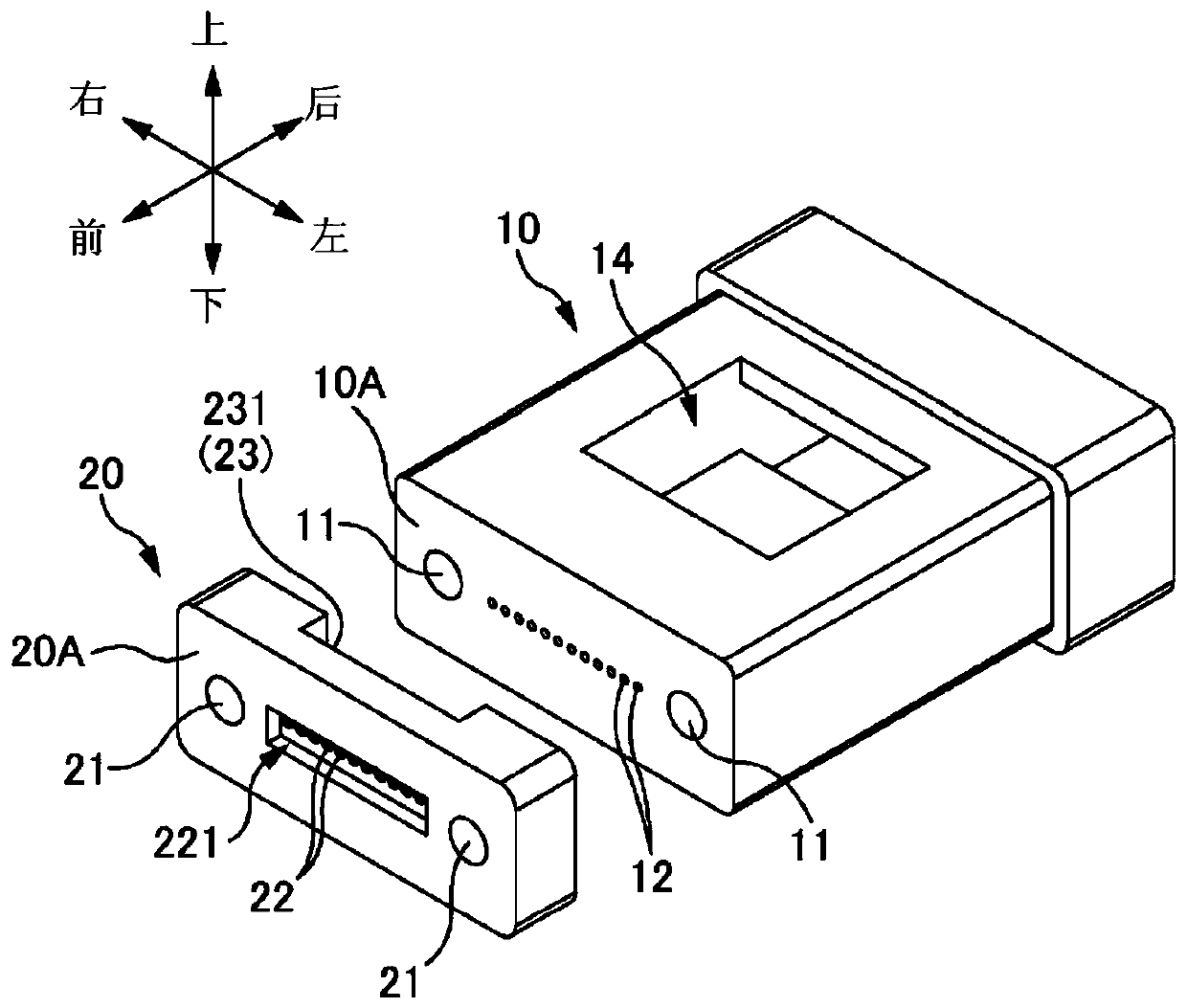
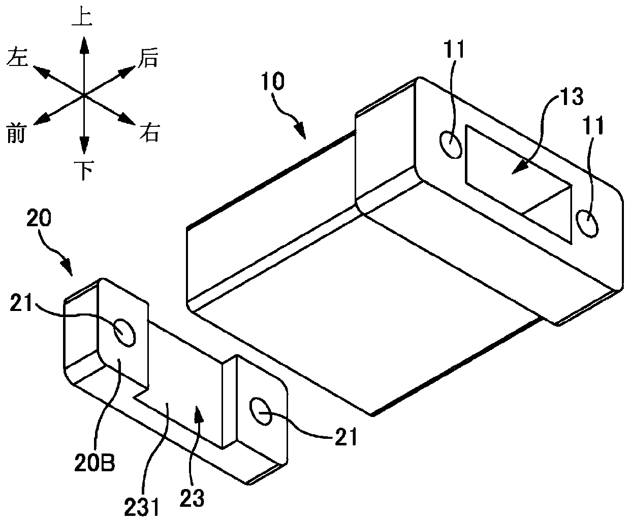
[0030] figure 1 It is an overall perspective view of the ferrule structure 1 of the first embodiment. Figure 2A and Figure 2B It is an exploded perspective view of the ferrule structure 1 of the first embodiment.
[0031] In the following description, each direction is defined as shown in the figure. That is, assuming that the direction of the fiber hole 12 is referred to as the "front-back direction", the optical fiber 3 inserted into the fiber hole 12 (refer to Figure 4B and Figure 4C ) side of the end face (or the side of the lens plate 20 when viewed from the ferrule main body 10) is referred to as "front", and the opposite side is referred to as "rear". In addition, the direction in which the two guide holes 21 are arranged is referred to as "left-right direction", the right side when viewed from the rear side to the front side is referred to as "right", and the opposite side is referred to as "left". In addition, let t...
no. 2 approach =
[0070] === Second Embodiment ===
[0071] In the first embodiment described above, by forming the concave portion 23 in the lens plate 20 , the matching agent filling portion 1A is formed between the opening surface of the fiber hole 12 of the ferrule body 10 and the contact surface 231 of the lens plate 20 . Clearance. However, by forming the recess 15 in the ferrule body 10 , a gap as the mating agent filling portion 1A may be formed between the opening surface of the fiber hole 12 of the ferrule body 10 and the contact surface of the lens plate 20 .
[0072] Figure 7A It is an overall perspective view of the ferrule structure 1 of the second embodiment. Figure 7B It is an exploded perspective view of the ferrule structure 1 of the second embodiment.
[0073] Similar to the first embodiment, the ferrule body 10 has a guide hole 11 , an optical fiber hole 12 , an optical fiber insertion port 13 , and an adhesive filling portion 14 , and also has a concave portion 15 .
...
PUM
 Abstract
Description
Claims
Application Information
 - R&D
- Intellectual Property
- Life Sciences
- Materials
- Tech Scout
- Unparalleled Data Quality
- Higher Quality Content
- 60% Fewer Hallucinations
Browse by: Latest US Patents, China's latest patents, Technical Efficacy Thesaurus, Application Domain, Technology Topic, Popular Technical Reports.
© 2025 PatSnap. All rights reserved.Legal|Privacy policy|Modern Slavery Act Transparency Statement|Sitemap|About US| Contact US: help@patsnap.com


