Ultra-high speed drawing equipment for bonding tin-plating alloy wire

An alloy wire and ultra-high-speed technology, which is applied in the field of ultra-high-speed wire drawing equipment for bonded tin-plated alloy wire, can solve the problems of wire drawing die disassembly and replacement, inconvenient replacement, increased production difficulty and production cost, and affect work efficiency. The effect of selecting limitations, improving work effects, and improving production efficiency

Inactive Publication Date: 2019-06-25
JIANGXI FUHONG METAL CO LTD
View PDF12 Cites 3 Cited by
  • Summary
  • Abstract
  • Description
  • Claims
  • Application Information

AI Technical Summary

Problems solved by technology

[0002] The metal wire drawing machine belongs to the pre-processing equipment for the production of standard parts and other metal products. The internal metallographic structure, surface finish and straightening degree all meet the raw material processing requirements required for the production of standard parts and other metal products. Among them, the important part to realize its diameter change is the wire drawing die, and the wire is formed to the required diameter after passing through the wire drawing die; However, most of the existing wire drawing machines only have one wire drawing die, and the wire drawing die can be replaced according to different wire drawing requirements, but the disassembly and replacement of the wire drawing die is inconvenient, which affects the work efficiency; Drawing processing leads to slow drawing speed, and also causes obvious limitations on the selection of wire rods, increasing production difficulty and production costs

Method used


Image

  • Ultra-high speed drawing equipment for bonding tin-plating alloy wire
  • Ultra-high speed drawing equipment for bonding tin-plating alloy wire
  • Ultra-high speed drawing equipment for bonding tin-plating alloy wire

Examples


Embodiment Construction

[0025] The technical solutions of the present invention will be further described below in conjunction with the accompanying drawings and through specific implementation methods.

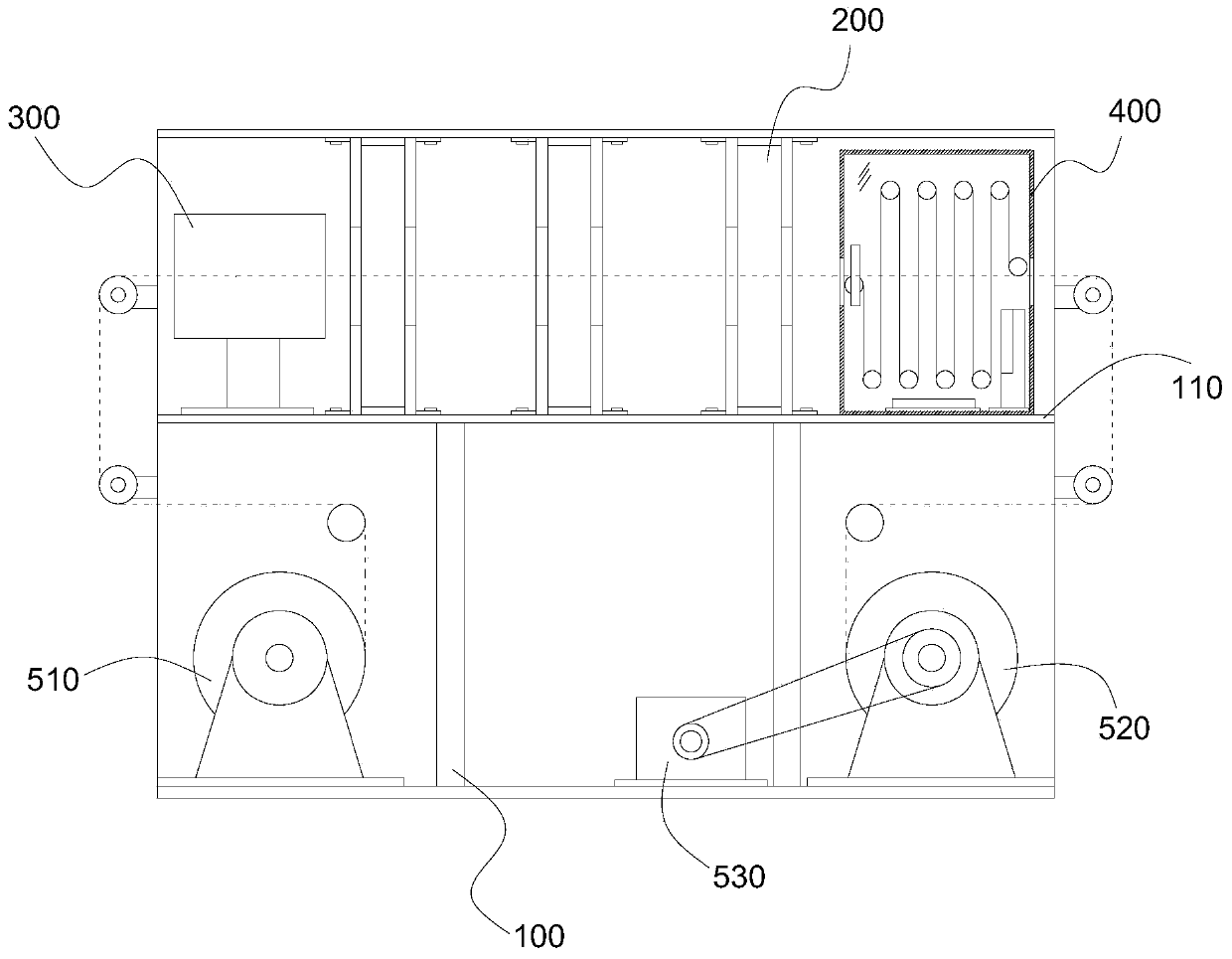
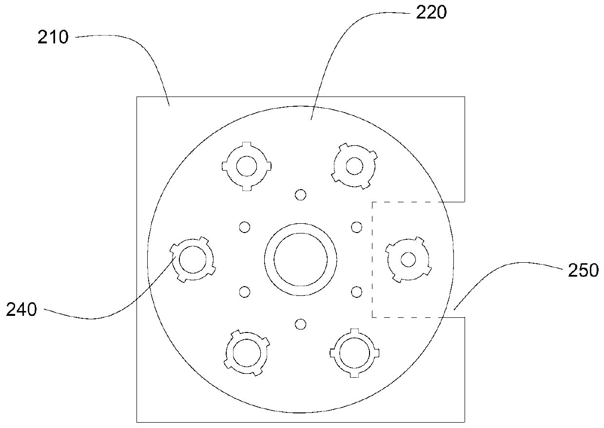
[0026] Such as figure 1 , figure 2 As shown, a specific embodiment of the present invention discloses a bonded tin-plated alloy wire ultra-high-speed wire drawing equipment, including a frame 100 and a workbench 110 fixed on the frame 100, the workbench 110 At least two wire drawing die mechanisms 200 are arranged on the top surface, and the wire drawing die mechanisms 200 are arranged side by side. One end of the workbench 110 is provided with a preheating pipe 300, and the other end is provided with a cooling box 400. Below the workbench 110 A pay-off wheel 510 and a take-up wheel 520 are provided, and the take-up wheel 520 is driven by a drive motor 530, and the bonding wire released by the pay-off wheel 510 passes through the preheating tube in turn under the guidance of a plurality of guide w...


PUM


Abstract

The invention provides ultra-high speed drawing equipment for a bonding tin-plating alloy wire. The ultra-high speed drawing equipment for the bonding tin-plating alloy wire comprises a worktable; atleast two drawing mould mechanisms are arranged on the top surface of the worktable and are arranged in parallel; a preheating tube is arranged at one end of the worktable; a cooling box is arranged at the other end of the workable; a wire unwinding wheel and a wire winding wheel are arranged below the worktable; the wire winding wheel is driven by a driving motor; each drawing mould mechanism comprises two clamping plates which are arranged oppositely; a mould mounting disc is arranged between the two clamping plates; the mould mounting disc is rotatably erected between the two clamping plates; a plurality of mounting grooves are formed in the mould mounting disc; a plurality of mounting grooves are distributed in a circumferential array around the circle centre of the mould mounting disc; a drawing mould is mounted in each mounting groove; the diameters of forming holes of various drawing moulds are different; the replacement of the drawing mould is realized by rotating the mould mounting disc so as to produce bonding wires with different diameter requirements; and multi-stage drawing and pulling treatment can be performed on the wires, so that steady wire drawing work is ensured, and the wire drawing speed is effectively improved.

Description

technical field [0001] The invention relates to the field of wire drawing equipment, and more specifically, relates to an ultra-high-speed wire drawing equipment for bonding tin-plated alloy wires. Background technique [0002] The metal wire drawing machine belongs to the pre-processing equipment for the production of standard parts and other metal products. The internal metallographic structure, surface finish and straightening degree all meet the raw material processing requirements required for the production of standard parts and other metal products. Among them, the important part to realize its diameter change is the wire drawing die, and the wire is formed to the required diameter after passing through the wire drawing die; However, most of the existing wire drawing machines only have one wire drawing die, and the wire drawing die can be replaced according to different wire drawing requirements, but the disassembly and replacement of the wire drawing die is inconveni...

Claims


Application Information

Patent Timeline
Patent Type & Authority Applications(China)
IPC IPC(8): B21C1/04B21C9/00
Inventor 欧阳艳青
Owner JIANGXI FUHONG METAL CO LTD
Why Eureka
Try Eureka