
Novel wire conveying device for numerically-controlled wire cutting electrical discharge machine

A technology of wire cutting and spark machine, applied in the direction of electric processing equipment, metal processing equipment, electrode manufacturing, etc., can solve the problems affecting the cutting processing accuracy, and achieve the effect of improving utilization rate, reducing vibration and reducing operation difficulty

Pending Publication Date: 2019-06-25
施光辉
View PDF0 Cites 2 Cited by
  • Summary
  • Abstract
  • Description
  • Claims
  • Application Information

AI Technical Summary

Problems solved by technology

[0002] At present, the CNC wire-cut spark machine device is a molybdenum wire wound on a wire drum, reciprocating in a closed polygonal state, so the tension of the molybdenum wire is loose and tight, and the molybdenum wire will resonate during high-speed rotation, so It will affect the cutting precision

Method used

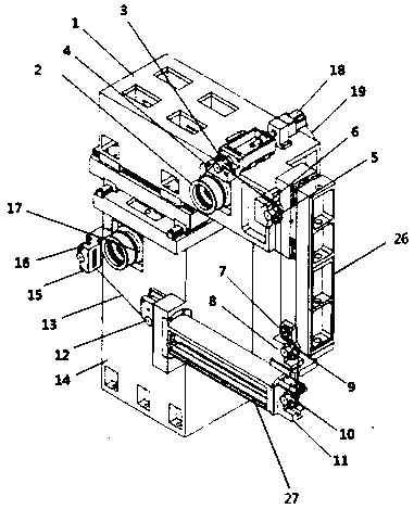
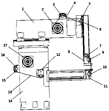
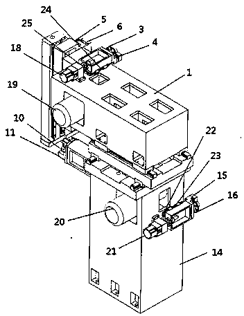

Image

  • Novel wire conveying device for numerically-controlled wire cutting electrical discharge machine
  • Novel wire conveying device for numerically-controlled wire cutting electrical discharge machine
  • Novel wire conveying device for numerically-controlled wire cutting electrical discharge machine

Examples


Embodiment

[0022] Example: such as Figure 1-3 As shown, the present invention provides a novel CNC wire-cutting spark machine wire transport device, comprising an upper frame 1 and a lower frame 14 stacked up and down, and an upper wire drum 2 and a lower wire drum are respectively installed on the upper and lower frames 17. The upper wire drum 2 and the lower wire drum 17 are located on the same plane of the frame, connected by molybdenum wire 13, and move synchronously under the drive of the motor; the two ends of the molybdenum wire 13 are respectively wound on the upper and lower wire drums The molybdenum wire 13 is connected to the upper wire wheel 3 after bypassing the upper wire drum 2, and is connected to the fixed guide wheel 5 through the upper wire wheel 3; On the wheel seat frame 4, the upper fixed guide wheel 5 is installed on the upper fixed wheel seat frame 6 at the top of the upper wire frame 26 on the side of the upper and lower frame; The bridge guide wheel 7 is insta...


PUM


Abstract

The invention discloses a novel wire conveying device for a numerically-controlled wire cutting electrical discharge machine. The device is characterized in that a molybdenum wire is connected and coils two wire rollers, and the two wire rollers are rotated by reciprocating to wind the molybdenum wire; after current is introduced and pulse current is produced by the molybdenum wire, metal steel can be cut; and different complex shapes can be formed by cutting under numerical control of a computer. The device achieves the following beneficial effects: 1, the two wire rollers are connected through one molybdenum wire, and the molybdenum wire coils the wire rollers and the wire rollers are rotated by reciprocating, so that resonance is not produced; 2, one of the two wire rollers pulled by the molybdenum wire is rotated by reciprocating in a driving wheel form, and another one is rotated by reciprocating in a driven wheel form during working; and the molybdenum wire is repeatedly utilized, so that the utilization rate of the molybdenum wire is increased; 3, the driven wheel is rotated with damping, so that the tension of the molybdenum wire is constant, so that the processing stability in working is ensured; 4, a motor is fixed to a rack and is rotated by reciprocating; the bolt line spacing of the molybdenum wire coiling the wire rollers is controlled through a wire arranging wheel, so that the vibration caused by reciprocating moving of the wire rollers can be reduced; and 5, the two wire rollers are on the same plane, so that the difficulty in operation is extremely reduced.

Description

technical field [0001] The invention relates to the technical field of cutting machinery, in particular to a novel wire-feeding device for a numerically controlled wire-cut spark machine. Background technique [0002] At present, the CNC wire cutting spark machine device is a molybdenum wire wound on a wire drum, reciprocating in a closed polygonal state, so the tension of the molybdenum wire is loose and tight, and the molybdenum wire will resonate during high-speed rotation, so It will affect the cutting precision. Contents of the invention [0003] The invention solves the defect that the numerical control wire cutting spark machine device reciprocates in a closed polygonal state, so the tension of the molybdenum wire is loose and sometimes tight, and during high-speed rotation, the molybdenum wire will resonate, which will affect the cutting precision. , to provide a new type of CNC wire cutting EDM wire feeding device. [0004] In order to solve the above-mentioned ...

Claims


Application Information

Patent Timeline
Patent Type & Authority Applications(China)
IPC IPC(8): B23H7/10
Inventor 施光辉
Owner 施光辉
Learn More