

Part installation tool
A technology for installing tools and parts, which is applied in the field of liquid rocket engine assembly, can solve the problems of damaged welded bellows, damping band jamming, and inability to ensure the alignment of assembly relations, etc., and achieves the effects of small size, simple assembly, and light weight
- Summary
- Abstract
- Description
- Claims
- Application Information
AI Technical Summary
Problems solved by technology
Method used
Image

Examples
Embodiment 1
[0030] The present invention will be described in detail below in conjunction with the accompanying drawings and specific embodiments.
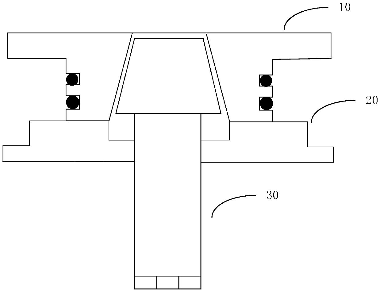
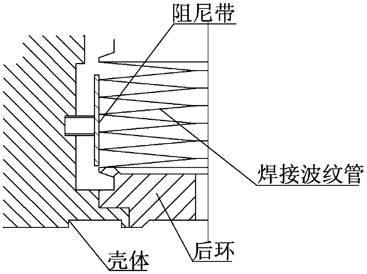
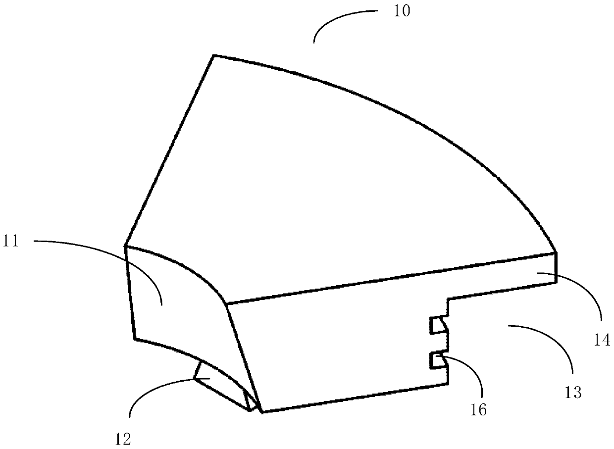
[0031] Such as Figure 1-Figure 6 as shown, figure 1 Schematic diagram of the structure of the parts installation tool provided by the present invention; figure 2 It is a schematic diagram of the assembly relationship mentioned in the present invention; image 3 Schematic representation of the split chuck provided for the present invention Figure 1 ; Figure 4 Schematic representation of the split chuck provided for the present invention Figure II ; Figure 5 A schematic diagram of the base provided by the present invention; Image 6 Schematic diagram of the mandrel provided for the present invention. The present invention provides a component installation tool, comprising a base 20, a plurality of split chucks 10 and a mandrel 30, wherein the base 20 has a threaded hole 21, the mandrel 30 has an external thread, and the mandrel 30 ...
PUM
 Abstract
Description
Claims
Application Information