Straddle type monorail PC track girder construction method inside circular cross section tunnel

A straddle-type monorail and construction method technology, which is applied in the direction of tracks, roads, buildings, etc., can solve the problems that the beam erecting machine and the beam transporter cannot walk on the arc surface, the track has a large manpower and material cost, and an additional process is added. , to achieve the effect of convenient and flexible horizontal adjustment, improving construction efficiency and reducing procedures

Inactive Publication Date: 2019-06-25
NO 1 CONSTR ENG CO LTD OF CHINA CONSTR THIRD ENG BUREAU CO LTD
5 Cites 3 Cited by

AI-Extracted Technical Summary

Problems solved by technology

[0004] However, the above two construction methods of the monorail PC track in the tunnel section have defects: when the track-type gantry method is used, the installation and removal of the track consumes a lot of manpower and material costs, and it is necessary to drill holes on the tunnel wall to install the track abutment. On the one hand, it damages the tunnel structure and causes quality...

Method used

In the present invention, described self-deformable tire type beam carrier vehicle 3 comprises fuselage main body and is located at the running gear B32 of fuselage main body bottom, and running gear B32 comprises fixed frame B and road wheel B, and the axle of road wheel B One end is connected with the fixed frame B, and the angle between the axle of the traveling wheel B and the horizontal plane is adjustable. Preferably, the self-deformable tire-type beam transport vehicle 3 is provided with a straddle-type monorail PC track beam fixing device 31 to prevent the PC track beam 2 from rolling over and slipping during transportation. In the present embodiment, the fuselage main body of the self-deformable tire type beam transport vehicle 3 is a prior art, and will not be described in detail here; the walking device B32 adopts variable angle adjustment technology, and the rubber tire can adjust the angle, in arc shape, horseshoe shape, Walking, steering, transportation and other operations on flat and other basic surfaces. The bottom space of the self-deformable tire-type beam transporter 3 can pass through the concrete anchor box base 5 smoothly, and at the same time, the entire self-deformable tire-type beam transporter 3 can smoothly enter the self-deformable tire-type beam erecting machine 1, ensuring self-deformation. The passability of the deformed tire type beam transporter 3 in the process of beam transport and beam feeding. The self-deformable tire type beam transport vehicle 3 can also realize the transportation of materials such as mixing tanks, concrete and steel bars, tools and equipment. This multifunctional transport vehicle can freely pass through tunnels of various shapes and types, and the vehicles can also be freely combined to realize the transportation of large components and special components.
In the present invention, described self-deformable tire-type beam erecting machine 1 comprises main beam 11, running gear A13, lateral clamping device 14 and hoisting mechanism, and described main beam 11 is a door frame structure as a whole, and is composed of cross bar and It is composed of ver...

Abstract

The invention discloses a straddle type monorail PC track girder construction method inside a circular cross section tunnel. The method comprises the following steps of providing a girder erection machine and a girder transporting vehicle capable of walking on the hook face; a PC track girder is fixedly installed on the girder transporting vehicle, and the girder erection machine is put in place;the girder transporting vehicle transports the PC track girder into the girder erection machine; a transverse clamping device of the girder erection machine is started, the PC track girder is lifted,and the girder transporting vehicle exits from the circular cross section tunnel; the girder erection machine erects the PC track girder according to a design construction drawing, the girder transporting vehicle is returned to transport a next PC track girder; after erection of the girder erection machine is completed, the next PC track girder is erected when the girder erection machine is put inplace forwards. The method has the advantages that walking devices of an existing girder erection machine and a girder transporting vehicle are modified, the modified girder transporting vehicle andthe girder erection machine achieve erection of the straddle type monorail PC track girder inside the circular cross section tunnel, the construction cost is low, operation and transition are flexible, cross operation can be performed, construction organizations are flexible, and the construction efficiency is high.

Application Domain

Railway tracks

Technology Topic

Shop drawingStraddle +2

Image

  • Straddle type monorail PC track girder construction method inside circular cross section tunnel
  • Straddle type monorail PC track girder construction method inside circular cross section tunnel
  • Straddle type monorail PC track girder construction method inside circular cross section tunnel

Examples

  • Experimental program(1)

Example Embodiment

[0033] In order to better understand the present invention, the present invention will be further described below in conjunction with the accompanying drawings and specific embodiments.
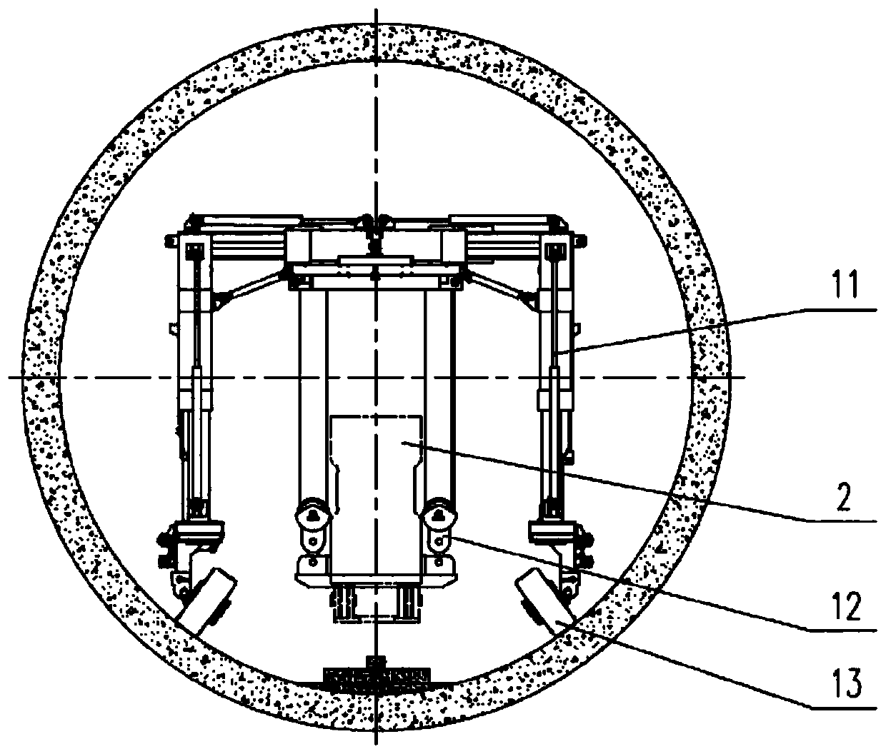
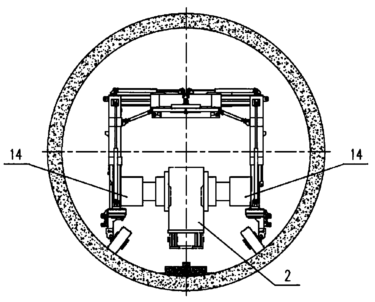
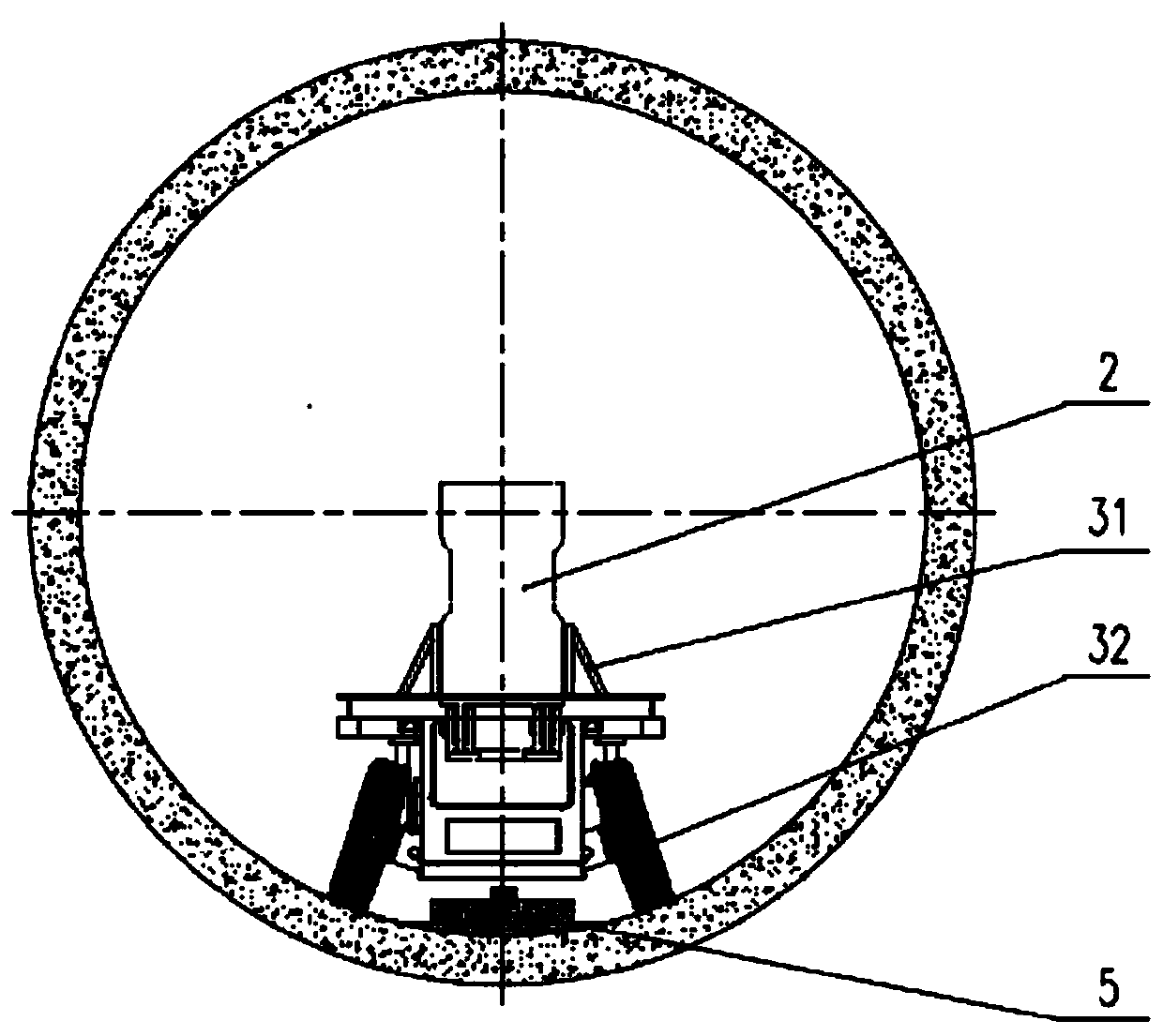
[0034] like Figure 5 A construction method for a straddle-type monorail PC track beam in a tunnel with a circular section as shown, comprising the following steps:
[0035] Step 1. Provide a self-deformable tire-type beam erecting machine 1 and a self-deformable tire-type beam transport vehicle 3 that can walk on curved surfaces;
[0036] Step 2: Install and fix the PC track beam 2 on the self-deformable tire-type beam transport vehicle 3, and drive the self-deformable tire-type beam erecting machine 1 into the circular cross-section tunnel 4 to be in place;
[0037] Step 3: The self-deformable tire-type beam transport vehicle 3 transports the PC track beam 2 into the self-deformable tire-type beam erecting machine 1. At this time, the self-deformable tire-type beam transport vehicle 3 is located in the transverse clamp holding device 14 below;
[0038] Step 4. Start the hoisting device 12 of the self-deformable tire-type beam-erecting machine 1 to lift the PC track beam 2. After the PC track beam 2 falls on the concrete anchor box base 5, start the transverse clamp of the self-deformable tire-type beam-erecting machine 1 The holding device 14 is used for horizontal adjustment, and at the same time, the self-deformable tire type beam transport vehicle 3 exits the circular cross-section tunnel 4;
[0039] Step 5. The self-deformable tire-type beam erecting machine 1 erects the PC track beam 2 according to the design and construction drawing, and the self-deformable tire-type beam transporter 3 returns to transport the next PC track beam 2;
[0040] Step 6: After the self-deformable tire type beam erecting machine 1 is erected, erect the next PC track beam 2 in place forward.
[0041] In the present invention, the self-deformable tire-type beam erecting machine 1 includes a main beam 11, a traveling device A13, a lateral clamping device 14, and a hoisting mechanism. The vertical rods on both sides of the rod are composed of horizontal rods and vertical rods. At the bottom of the bottom, the walking device A13 includes a fixed frame A and a walking wheel A. One end of the axle of the walking wheel A is connected to the fixed frame A, and the angle between the wheel axle of the walking wheel A and the horizontal plane is adjustable; The wire rope pulley winch mechanism. In this embodiment, the cross bars and vertical bars of the self-deformable tire-type beam-erecting machine 1 are all retractable structures, which can quickly realize span and height adjustments to adapt to different tunnel sections; the walking of the self-deformable tire-type beam-erecting machine 1 The device A13 adopts variable angle adjustment technology, and the wheel axle angle of its traveling wheel is adjustable (the angle of the traveling wheel is adjustable), and it can carry out operations such as walking, turning, hoisting, etc. on arc-shaped, horseshoe-shaped, plane and other base surfaces; The horizontal clamping device 14 is hydraulically driven, so that the horizontal adjustment is more convenient and flexible when the straddle-type monorail PC track beam 2 falls on the concrete anchor box base 5 . During the operation, the track beam is first lifted by the hoisting mechanism, and when the track beam falls to the base and needs to be adjusted, the horizontal clamping device 14 is used for horizontal adjustment.
[0042]In the present invention, the self-deformable tire type beam transport vehicle 3 includes a fuselage body and a running device B32 arranged at the bottom of the fuselage body. The running device B32 includes a fixed frame B and a walking wheel B. The frame B is connected, and the angle between the axle of the walking wheel B and the horizontal plane is adjustable. Preferably, the self-deformable tire-type beam transport vehicle 3 is provided with a straddle-type monorail PC track beam fixing device 31 to prevent the PC track beam 2 from rolling over and slipping during transportation. In the present embodiment, the fuselage main body of the self-deformable tire type beam transport vehicle 3 is a prior art, and will not be described in detail here; the walking device B32 adopts variable angle adjustment technology, and the rubber tire can adjust the angle, in arc shape, horseshoe shape, Walking, steering, transportation and other operations on flat and other basic surfaces. The bottom space of the self-deformable tire-type beam transporter 3 can pass through the concrete anchor box base 5 smoothly, and at the same time, the entire self-deformable tire-type beam transporter 3 can smoothly enter the self-deformable tire-type beam erecting machine 1, ensuring self-deformation. The passability of the deformed tire type beam transporter 3 in the process of beam transport and beam feeding. The self-deformable tire type beam transport vehicle 3 can also realize the transportation of materials such as mixing tanks, concrete and steel bars, tools and equipment. This multifunctional transport vehicle can freely pass through tunnels of various shapes and types, and the vehicles can also be freely combined to realize the transportation of large components and special components.
[0043] In the present invention, the self-deformable tire-type beam erecting machine 1 and the self-deformable tire-type beam transport vehicle 3 adopt dual power supply technology of battery pack and power grid. The battery is used for power supply under daily working conditions, eliminating the need for on-board cables, and the grid power supply can also be used when the battery is out of power, which improves the reliability of the product. Noise pollution greatly improves the working environment.
[0044] In the case of long-distance construction, use the self-deformable tire type beam erecting machine 1 and the beam transport vehicle for construction; in the case of short-distance construction, you can directly use two self-deformable tire type beam erection machines 1 to realize the integration of PC track beam 2 transportation and erection , eliminating the need for self-deformable tire beam transport vehicles 3, such as Image 6 As shown, the construction cost is saved.
[0045] The above descriptions are only preferred embodiments of the present invention, and are not intended to limit the present invention. For those skilled in the art, the present invention may have various modifications and changes. Any modifications, equivalent replacements, improvements, etc. made within the spirit and principles of the present invention shall be included within the protection scope of the present invention.

PUM

no PUM

Description & Claims & Application Information

We can also present the details of the Description, Claims and Application information to help users get a comprehensive understanding of the technical details of the patent, such as background art, summary of invention, brief description of drawings, description of embodiments, and other original content. On the other hand, users can also determine the specific scope of protection of the technology through the list of claims; as well as understand the changes in the life cycle of the technology with the presentation of the patent timeline. Login to view more.

Similar technology patents

Classification and recommendation of technical efficacy words

  • Reduce construction costs

Nanometer drag reducer for sandstone surface pretreatment and preparation method of nanometer drag reducer

InactiveCN102838981AReduce construction costsThe preparation process is simple and easy
Owner:SHAANXI RES DESIGN INST OF PETROLEUM CHEM IND

Protected seam bottom plate upward comb-shaped drilled hole gas extraction method

ActiveCN102661167AReduce construction costsShorten mining cycle
Owner:CHINA UNIV OF MINING & TECH

Special vehicle signal priority control method based on global position system (GPS)

InactiveCN103035129Areduce construction costsEasy equipment maintenance
Owner:JIANGSU ZHITONG TRANSPORTATION TECH +1
Why Eureka
Try Eureka