Display panel and display device

A display panel and display area technology, which is applied to identification devices, instruments, etc., can solve the problem of the large size of the lower frame of the display panel, and achieve the effects of narrowing the frame, increasing the binding area, and reducing the vertical length.

Active Publication Date: 2019-06-25
WUHAN TIANMA MICRO ELECTRONICS CO LTD
View PDF14 Cites 20 Cited by
  • Summary
  • Abstract
  • Description
  • Claims
  • Application Information

AI Technical Summary

Problems solved by technology

For a display panel using a COF packaging process, the width of its lower border is mainly limited by the vertical size of the fanout area (fanout) and the binding area, and with the increase in the pixel density of the display panel, the vertical size of the fanout area and the binding area Difficult to scale down any further, resulting in a larger size for the lower bezel of the display panel

Method used


Image

  • Display panel and display device
  • Display panel and display device
  • Display panel and display device

Examples


Embodiment Construction

[0022] The present invention will be further described in detail below in conjunction with the accompanying drawings and embodiments. It should be understood that the specific embodiments described here are only used to explain the present invention, but not to limit the present invention. In addition, it should be noted that, for the convenience of description, only some structures related to the present invention are shown in the drawings but not all structures.

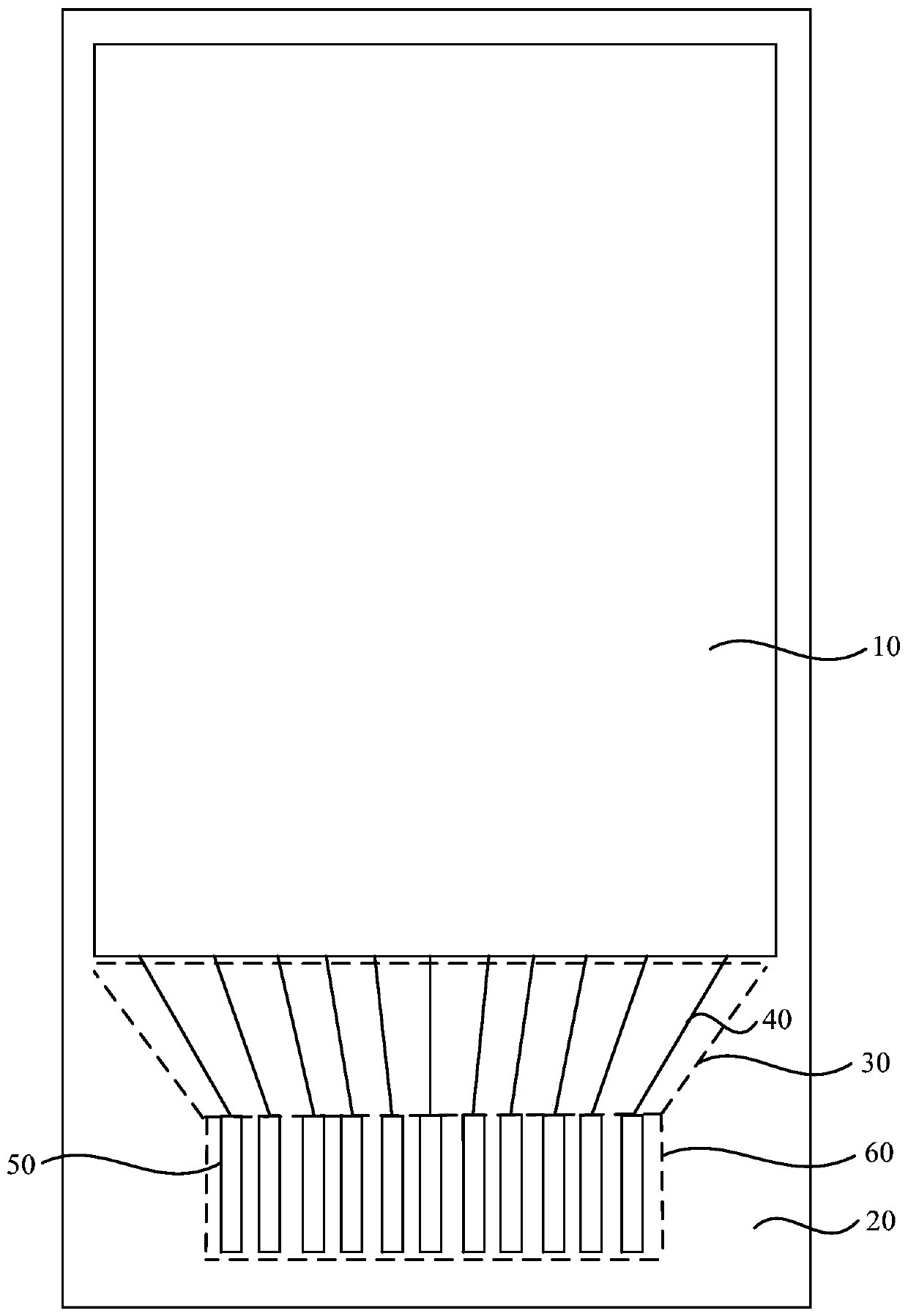
[0023] Usually, such as figure 1 As shown, the display panel includes a display area 10 and a non-display area 20, the display area 10 is used for displaying, and the non-display area 20 includes a fan-out line 40 drawn from the display area 10 and at least one row of bars correspondingly connected to the fan-out line 40 Shaped bonding pads 50, each row of bonding pads 50 are arranged in parallel in the lateral direction, the fan-out area 30 is formed in the area where the fan-out wiring 40 is located, and the bon...


PUM


Abstract

The embodiment of the invention discloses a display panel and a display device. The display panel comprises a display area and a non-display area surrounding the display area, the non-display area isprovided with a plurality of fan-out wires and a plurality of first binding bonding pads, and the fan-out wires are led out from the display area and electrically connected with the first binding bonding pads; the first binding bonding pads are arranged in a first direction, and each first binding bonding pad comprises a first bonding pad part and a second bonding pad part; the first end of the first bonding pad part in each first binding bonding pad is in electrical contact with the first end of the corresponding second bonding pad part, the second end of each second bonding pad part is electrically connected with the corresponding fan-out wire, and the length direction of the first bonding pad parts intersects with the length direction of the second bonding pad parts; an acute angle between the long edge of each second bonding pad part and the connected fan-out wire is smaller than 30 degrees. According to the technical scheme, a frame of the display panel is further narrowed while the effective binding area of the first binding pads is ensured.

Description

technical field [0001] Embodiments of the present invention relate to the technical field of display panels, and in particular, to a display panel and a display device. Background technique [0002] With the wide application of electronic products such as mobile phones, more and more requirements are placed on the non-display area of ​​the display panel, and narrow bezels have become a development trend of electronic products. [0003] In order to achieve a narrow frame, the current chip packaging mainly adopts chip on film (COF, Chip On Film) and chip on plastic (COP, Chip On Pi) packaging technology. For a display panel using a COF packaging process, the width of its lower border is mainly limited by the vertical size of the fanout area (fanout) and the binding area, and with the increase in the pixel density of the display panel, the vertical size of the fanout area and the binding area It is difficult to shrink any further, resulting in a larger size of the lower bezel ...

Claims


Application Information

Patent Timeline
Patent Type & Authority Applications(China)
IPC IPC(8): G09F9/30
Inventor 朱家柱
Owner WUHAN TIANMA MICRO ELECTRONICS CO LTD
Why Eureka
Try Eureka