Target point positioning navigation system and method

A technology for positioning navigation and target point, which is applied in the field of target point positioning and navigation system, can solve the problems of inaccurate positioning, complicated and time-consuming operation, and the markers are easy to block each other, so as to ensure the detection effect, the operation is simple, and the operation of ultrasonic positioning is convenient. Effect

Pending Publication Date: 2019-06-28
付立功
View PDF0 Cites 3 Cited by
  • Summary
  • Abstract
  • Description
  • Claims
  • Application Information

AI Technical Summary

Problems solved by technology

[0006] The technical problem to be solved by the present invention is that the markers of the penetrating device on the existing positioning and navigation system are easy to block each other, resulting in inaccurate positioning and complex and time-consuming operations.

Method used


Image

  • Target point positioning navigation system and method
  • Target point positioning navigation system and method

Examples


Embodiment 1

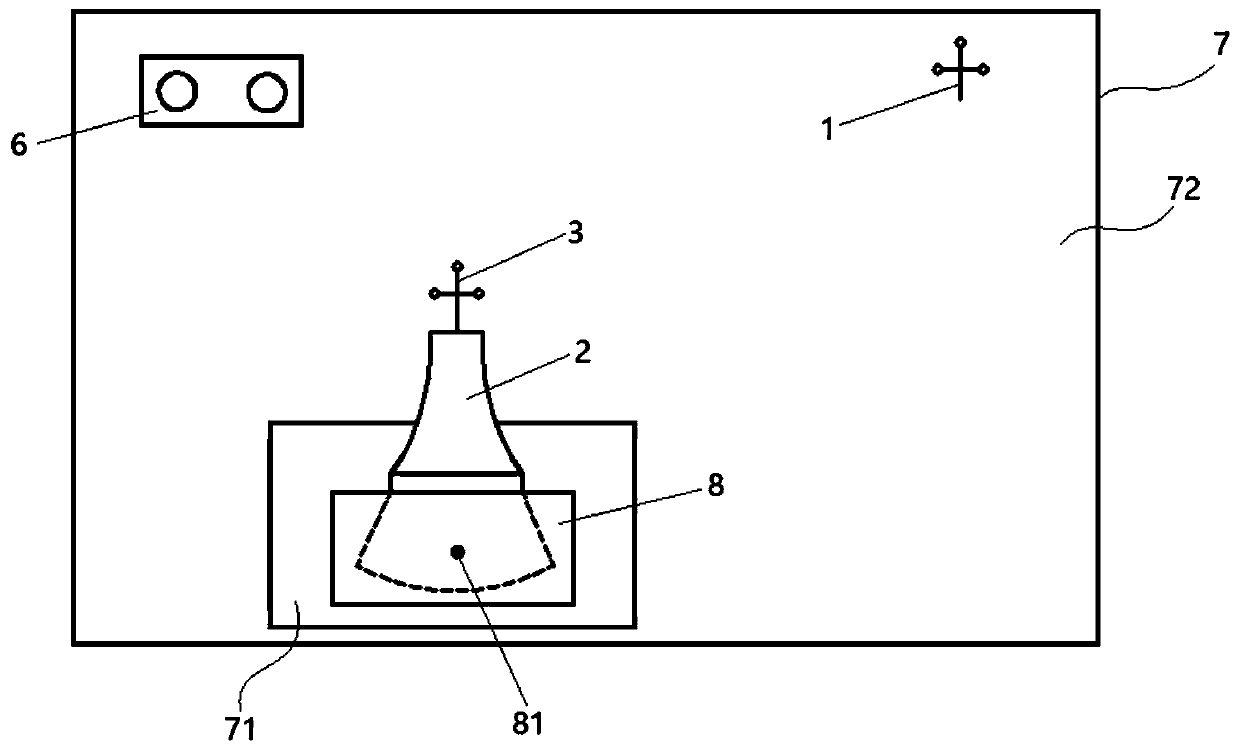
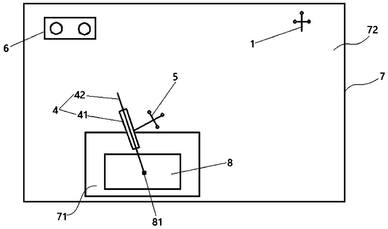
[0033] Such as figure 1 and figure 2 As shown, the target point positioning and navigation system provided by Embodiment 1 of the present invention includes a penetrating device, a positioning device and a navigation control device. The navigation control device includes a first marker 1 and a processing device. The positioning device includes a detection device 2 and is arranged on The second marker 3 on the detection device 2, the detection device 2 is in contact with the base object 8, and is used to determine the relative positional relationship between the target point 81 in the base object 8 and the second marker 3, and the processing device passes the first marker 1 and the second marker 3 The relative positional relationship between the second marker 3 determines the relative positional relationship between the target point 81 and the first marker 1, the penetrating device includes the probe rod assembly 4 and the third marker 5 arranged on the probe rod assembly 4, a...

Embodiment 2

[0049] When the target point positioning and navigation system of Embodiment 2 of the present invention is applied to the B-ultrasound positioning and puncture system of medical equipment, the detection equipment can use a B-ultrasound probe, the probe rod is a puncture needle, the basic object is the punctured body, and the target point is the punctured body the puncture point. The second marker is fixed on the B-ultrasound probe, and the puncture point in the punctured body is determined by the B-ultrasound probe, so as to calculate the spatial position of the puncture point relative to the second marker, and the processing device passes the first marker and the second marker The relative spatial position of the puncture point is calculated relative to the first marker. The third marker is fixed on the outer sleeve of the puncture needle. The processing device calculates the puncture point through the spatial position of the first marker and the third marker. The spatial pos...


PUM


Abstract

The invention relates to the technical field of navigation, in particular to a target point positioning navigation system and method. The target point positioning navigation system comprises a probingdevice, a positioning device and a navigation control device, wherein the navigation control device comprises a first marker and a processing device; the positioning device comprises a detection device and a second marker arranged on the detection device, wherein the detection device is in contact with a basic object and used for determining the relative positional relationship between a target point in the basic object and the second marker; the processing device determines the relative positional relationship between the target point in the basic object and the first marker according to therelative positional relationship between the first marker and the second marker; the probing device comprises a probe rod assembly and a third marker arranged on the probe rod assembly, and the processing device determines the relative positional relationship between the target point and the third marker through the relative positional relationship between the first marker and the third marker soas to control the probe rod assembly to reach the target point. Pollution to a puncture body and nearby areas is reduced, and the problem is avoided that the markers on the detection device and the probe rod assembly are mutually blocked.

Description

technical field [0001] The present invention relates to the technical field of positioning and navigation, in particular to a target point positioning and navigation system and method. Background technique [0002] In the current non-mechanical puncture navigation based on B-ultrasound, there are two types of technologies, one is electromagnetic-based navigation, and the other is optical-based navigation. [0003] The main principle of the existing optical-based navigation is to place a group of binocular stereo vision cameras in the puncture operation space, and at the same time install reflective marking balls on the B-ultrasound probe and puncture instruments. The reflective marking balls can guide the incident light along the Reflected in the direction of incidence, independent of the angle of incidence. The binocular camera is equipped with a near-infrared supplementary light device, which emits infrared light to illuminate the reflective marking ball, and recognizes t...

Claims


Application Information

Patent Timeline
Patent Type & Authority Applications(China)
IPC IPC(8): A61B17/34A61B34/20
Inventor 付立功马龙飞赵喆宋飞陈芳
Owner 付立功
Why Eureka
Try Eureka