
Portable ultrasonic cleaner

An ultrasonic and portable technology, applied in the field of ultrasonic cleaning, can solve the problem of inability to fundamentally remove stains, and achieve the effects of easy storage for a long time, reduced length, and strong cleaning effect.

Active Publication Date: 2019-06-28
CHONGQING VOCATIONAL INST OF ENG
View PDF9 Cites 2 Cited by
  • Summary
  • Abstract
  • Description
  • Claims
  • Application Information

AI Technical Summary

Problems solved by technology

[0004] However, during the ultrasonic cleaning process, due to cavitation, the shock wave generated when the bubbles close at the junction of the object and the cleaning liquid will cause the cleaning liquid around the object to form a turbulent flow. When cleaning holes or pipes with large length and small inner diameter , it is difficult for the stain to fall out of the hole or pipe under turbulent flow, and it is also difficult to wash out the stain in the hole or pipe due to the small inner diameter
Stains that have not flowed out will adhere to the original corners of the item again when the item is used for a long time, and the stain cannot be removed fundamentally

Method used


Image

  • Portable ultrasonic cleaner
  • Portable ultrasonic cleaner
  • Portable ultrasonic cleaner

Examples


Embodiment 1

[0036] Embodiment 1 is basically as attached figure 1 with figure 2 Shown:

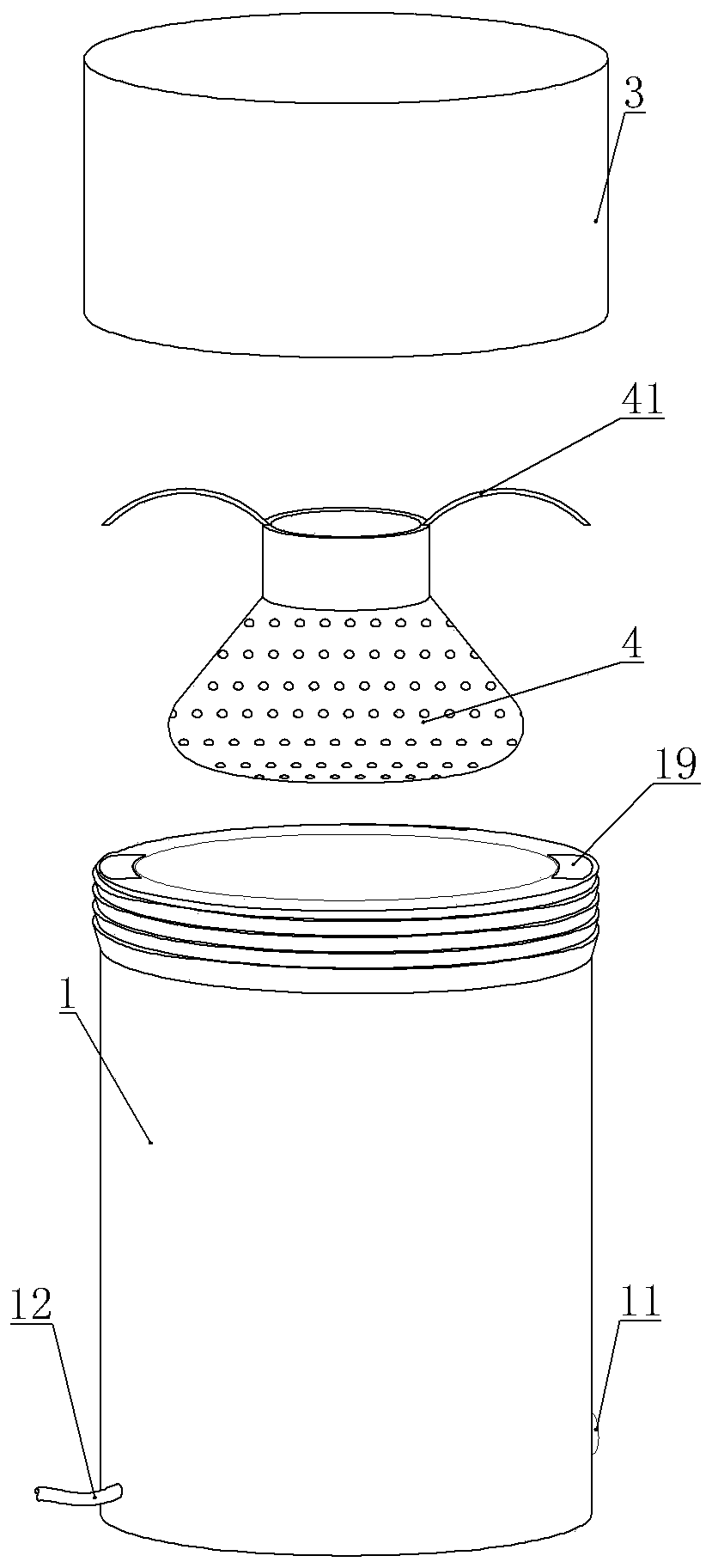
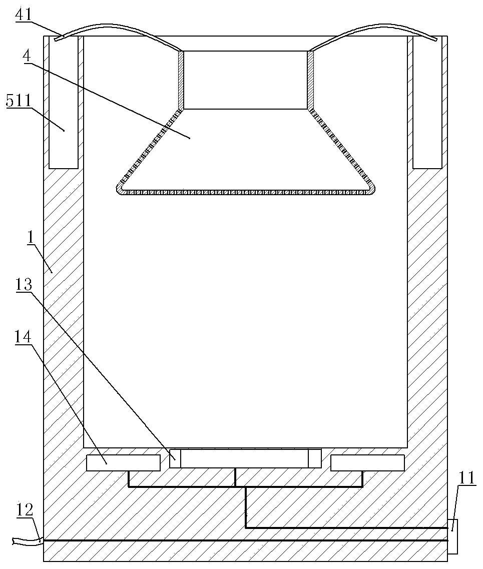
[0037] A portable ultrasonic cleaning machine includes a box body 1, a cleaning tank 4 and two ultrasonic generators 14. The box body 1 is provided with a cleaning chamber with an opening facing upwards, and the box body 1 is provided with a cover body 3 that closes the opening of the cleaning chamber. Specifically Yes, the cover body 3 can be directly covered on the box body 1, and the cover body 3 can be threadedly connected with the box body 1, and can also be hinged with the box body 1. The cover body 3 in this embodiment is connected with the box body by threaded connection body 1 connection. The cleaning tank 4 is located in the cleaning chamber, the top of the box body 1 is provided with two fixing tanks 19, the top of the cleaning tank 4 is provided with two folded parts 41, and the upper part of the folded parts 41 is folded outwards, and the cleaning tank 4 is put into the cleaning tank. ...

Embodiment 2

[0044] Embodiment 2 is basically as attached image 3 , Figure 4 with Figure 5 Shown:

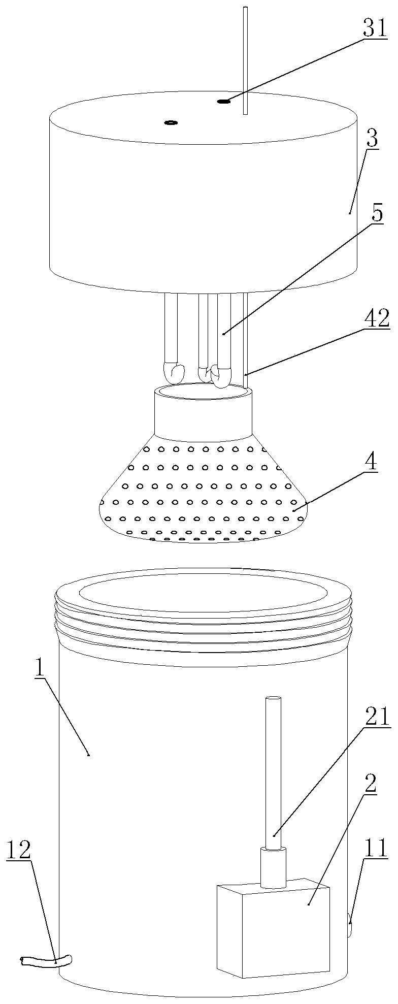
[0045] The difference from Example 1 is that the top of the box body 1 in this implementation is not provided with a fixing groove, the top of the cleaning tank 4 is not provided with a folded part 41, and the cleaning chamber in this embodiment is vertically provided with a connecting rod 42 , the upper end of the connecting rod 42 runs through the cover body 3 and can slide relative to the cover body 3. The connecting rod 42 is covered with a tension ring 32. The tension ring 32 is located between the connecting rod 42 and the cover body 3, and is glued to the cover body 3. Therefore, when the connecting rod 42 is pulled up or down, the connecting rod 42 can slide relative to the cover body 3, and when the connecting rod 42 is loosened, the elastic force of the tension ring 32 exerts lateral pressure on the connecting rod 42 to generate sufficient frictional force Make the connecting...


PUM


Abstract

The invention relates to the field of ultrasonic cleaning, in particular to a portable ultrasonic cleaner. The portable ultrasonic cleaner comprises a box body, an ultrasonic generator and a cleaningtank, wherein a cleaning cavity is formed in the box body, the cleaning tank is located in the cleaning cavity, and a cover body capable of sealing the cleaning cavity is arranged on the box body; anda heating cavity capable of containing a heat source is arranged at the lower part of the box body, and a cooling cavity capable of containing a cold source is arranged on the upper part or the coverbody of the box body, and the outer wall of the cooling cavity can be in contact with cleaning liquid in the cleaning cavity. According to the portable ultrasonic cleaner, flowing of the cleaning liquid can be strengthen, and stains can be promoted to fall out.

Description

technical field [0001] The invention relates to the field of ultrasonic cleaning, in particular to an ultrasonic cleaning machine. Background technique [0002] Ultrasound is a sound wave with a frequency higher than 20,000 Hz. It has good directionality and strong penetrating ability. At present, ultrasonic waves are widely used in the field of cleaning. During cleaning, the ultrasonic waves radiate forward in the cleaning liquid, causing the cleaning liquid to flow and generate tens of thousands of tiny bubbles. The tiny bubbles (cavitation nuclei) in the cleaning liquid vibrate under the action of the sound field. When the sound pressure reaches a certain value, the bubble grows rapidly and then closes suddenly. When the bubble closes, a shock wave is generated, and thousands of atmospheric pressures are generated around it, which will knock down the dirt on the surface of the object to be cleaned; The phenomenon of shock waves is called cavitation. Moreover, the above-...

Claims


Application Information

Patent Timeline
IPC IPC(8): B08B3/10B08B3/12B08B13/00
Inventor 黄朝阳耿浩楠李博
Owner CHONGQING VOCATIONAL INST OF ENG
Learn More