
Double-motor differential coupling power system

A power system and dual-motor technology, applied in the field of vehicle power systems, can solve problems such as design difficulties, increased costs, and large space occupation

Inactive Publication Date: 2019-06-28
GUANGZHOU XINYU POWER TECH CO LTD
View PDF0 Cites 1 Cited by
  • Summary
  • Abstract
  • Description
  • Claims
  • Application Information

AI Technical Summary

Problems solved by technology

[0002] With the development of electric vehicles, more and more electric vehicle users have put forward higher requirements for their power performance. For mid-to-high-end electric vehicles, it is difficult for a single high-power motor to take care of low-speed, low-power and high-torque driving in cities. conditions and high-speed high-power driving conditions, at the same time, a single high-power motor has caused difficulties for the cooling system, electronic control system and chassis suspension installation
How to solve the above problems, researchers in the field of electric drive proposed the joint drive of two small and medium power motors, which can effectively solve the problem of low speed and high speed driving efficiency by using two small and medium power motors. However, when a single motor works alone, its torque output characteristics are difficult to meet the performance requirements of mid-to-high-end vehicles. In addition, in high-speed combined drive, the gap between the two motors The problem of high-precision speed matching control becomes difficult and key
In addition, how to realize the parking and neutral gears has also become a design difficulty and a structure that increases costs dramatically

Method used


Image

  • Double-motor differential coupling power system

Examples


Embodiment Construction

[0013] The specific embodiments of the present invention will be further described below in conjunction with the accompanying drawings. It should be noted here that the descriptions of these embodiments are used to help understand the present invention, but are not intended to limit the present invention. In addition, the technical features involved in the various embodiments of the present invention described below may be combined with each other as long as they do not constitute a conflict with each other.

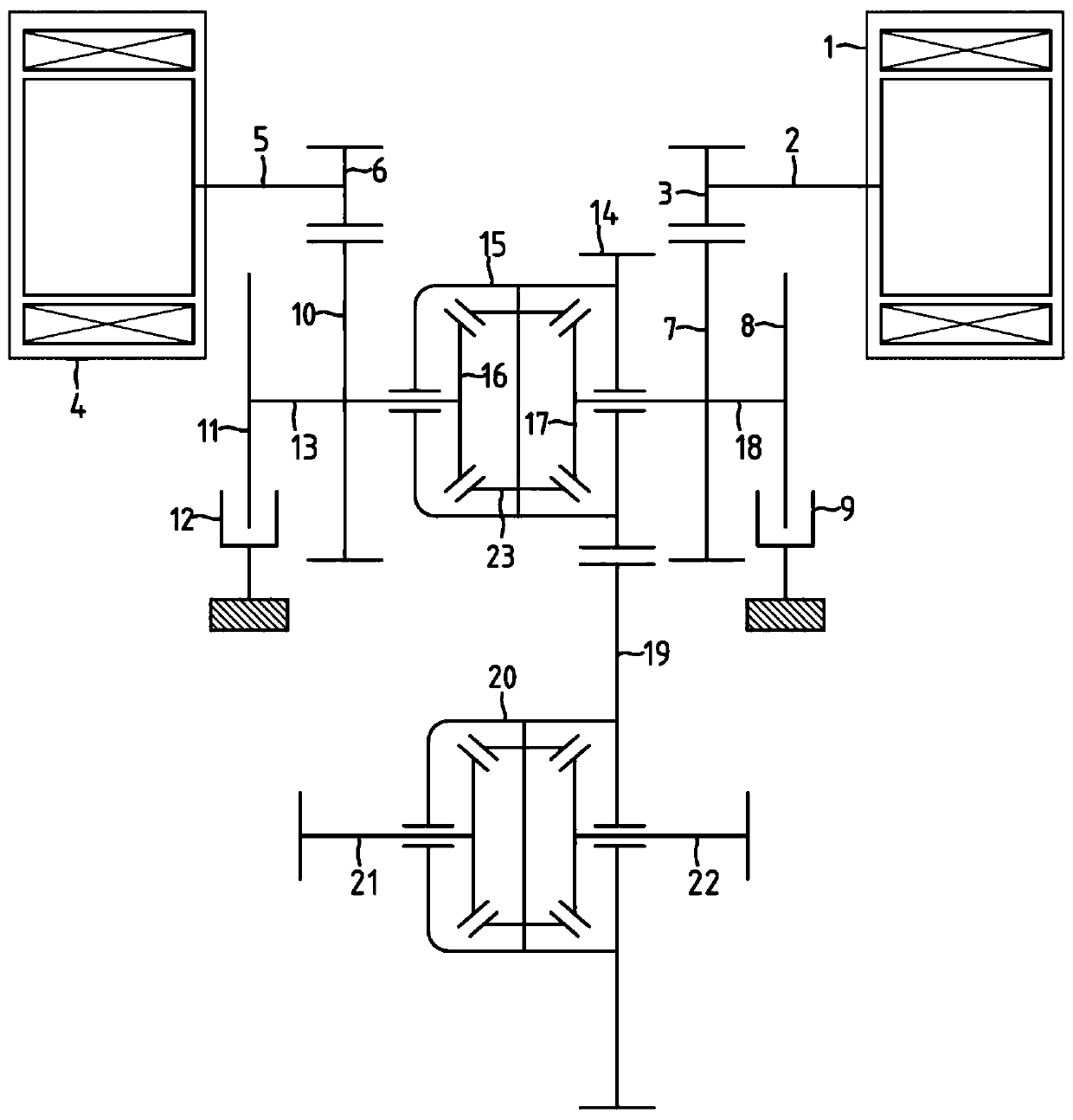
[0014] Such as figure 1 As shown, the dual-motor differential coupling power system consists of a first motor 1, a second motor 4, a multi-stage gear transmission pair, a first differential assembly 15, a second differential assembly 20, and two sets of brake components composition. The first motor 1 and the second motor 4 are arranged in parallel with the first differential gear assembly 15 and the second differential gear assembly 20 respectively.

[0015] The first...


PUM


Abstract

The invention discloses a double-motor differential coupling power system. In the double-motor differential coupling power system, two driving machines respectively or jointly drive two-stage differential components, when a first-stage gear and a coaxial bevel gear or a first-stage differential gear thereof are closed and / or released by selecting two corresponding sets of brakes, a plurality of driving modes such as motor independent driving, double-motor combined driving and the like are achieved, when one motor is driven by single low-speed large torque, the other motor is in a locking braking state, the following rotation loss of an idle motor in double-motor driving is reduced, and the service life of a motor bearing is effectively prolonged; the combined driving of allowing a large error matching range under the high rotating speed of the two motors is achieved, the requirement of high-precision rotating speed matching control of the two motors is greatly reduced, the cost of a control system is effectively reduced, the reliability of the system is effectively improved, the system has the advantages of high system efficiency, small size and weight, abundant driving modes, lowcost and the like, and is suitable for various pure electric vehicles.

Description

technical field [0001] The invention belongs to a vehicle power system, in particular to a power system adapted to an electric vehicle. Background technique [0002] With the development of electric vehicles, more and more electric vehicle users have put forward higher requirements for their power performance. For mid-to-high-end electric vehicles, it is difficult for a single high-power motor to take care of low-speed, low-power and high-torque driving in cities. conditions and high-speed high-power driving conditions, at the same time, a single high-power motor has caused difficulties in the cooling system, electronic control system and chassis suspension installation. How to solve the above problems, researchers in the field of electric drive proposed the joint drive of two small and medium power motors, which can effectively solve the problem of low speed and high speed driving efficiency by using two small and medium power motors. However, when a single motor works alo...

Claims


Application Information

Patent Timeline
IPC IPC(8): B60K17/16B60K17/356
Inventor 段福海王豫陈军
Owner GUANGZHOU XINYU POWER TECH CO LTD
Learn More