
Firefighting water supply system for high building

A technology for water supply systems and high-rise buildings, applied in water supply pipeline systems, buildings, water supply installations, etc., can solve the problems of low reliability of water supply systems, increased water supply risers, unfavorable maintenance and management, etc., and saves the high-rise space of super high-rise buildings. , The water supply system is simple and effective, and the maintenance is reliable and convenient.

Pending Publication Date: 2019-06-28
SANY AUTOMOBILE MFG CO LTD
View PDF0 Cites 5 Cited by
  • Summary
  • Abstract
  • Description
  • Claims
  • Application Information

AI Technical Summary

Problems solved by technology

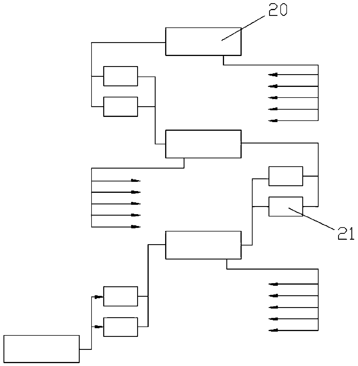
[0005] The main disadvantages of the above-mentioned connection to the fire water supply system include: 1) a pump room needs to be installed on the middle floor, and the layout of the pump group and pipelines needs to occupy a lot of valuable high-rise space; 3) The failure of any pump group in any partition will cause the upper partition to fail to supply water normally, and the reliability of the water supply system is low; 4) The equipment layout is scattered, which is not conducive to maintenance and management
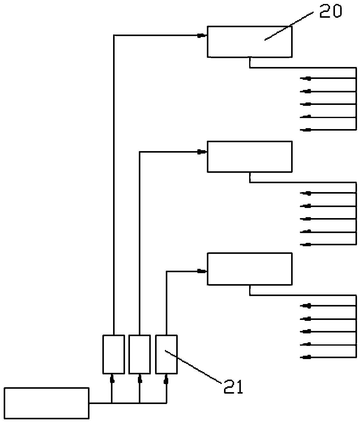
[0008] The main disadvantages of the aforementioned parallel partition fire water supply system include: the parallel water supply system will increase the number of water supply risers in the building, consume pipe materials, and increase costs
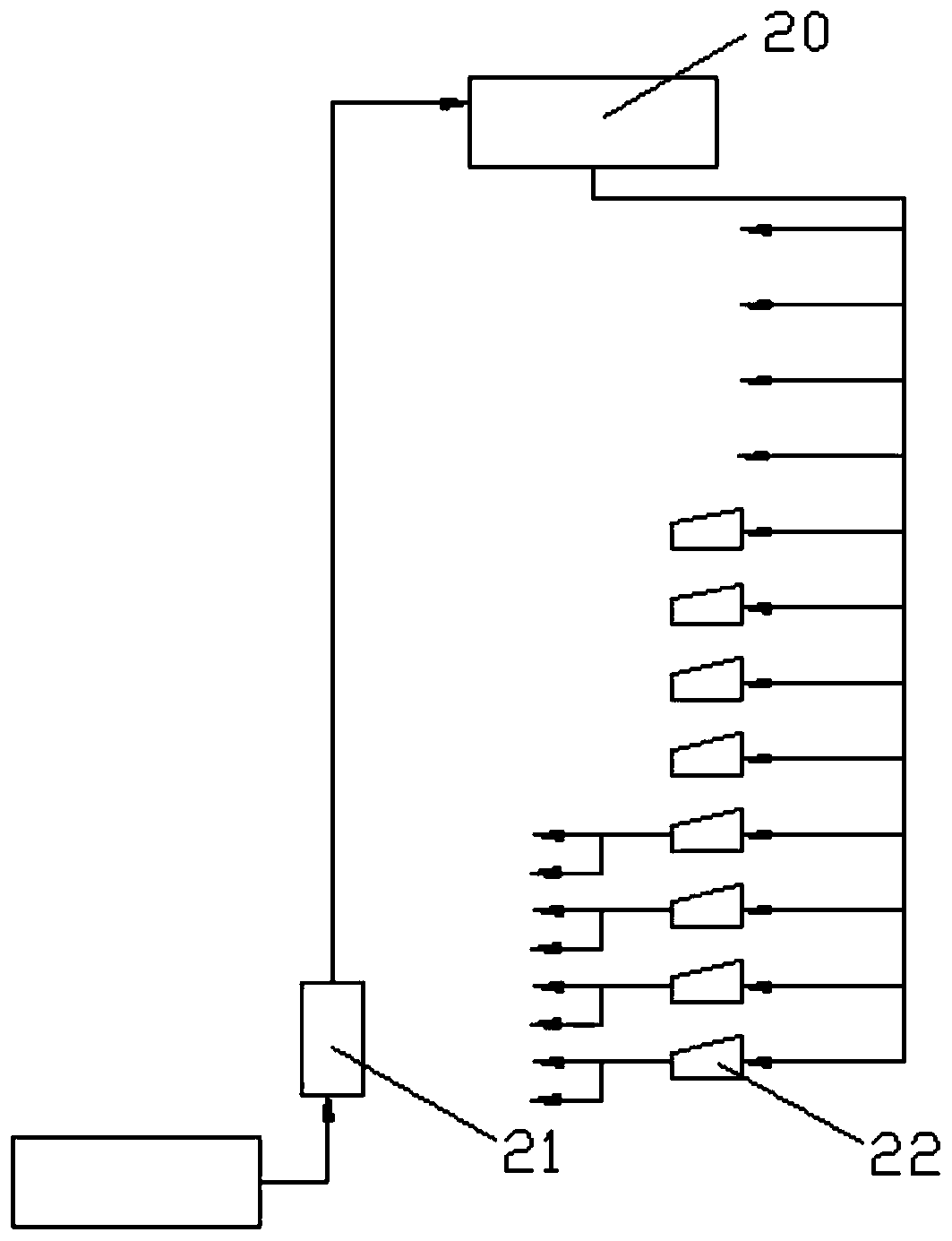
The disadvantage of this partitioned decompression fire protection water supply system is that it has high requirements for water pump head and water supply pipeline pressure resistance, and this method is only suitable for high-rise buildings no higher than 200 meters

Method used


Image

  • Firefighting water supply system for high building
  • Firefighting water supply system for high building
  • Firefighting water supply system for high building

Examples


Embodiment Construction

[0031] In order to understand the above-mentioned purpose, features and advantages of the present invention more clearly, the present invention will be further described in detail below in conjunction with the accompanying drawings and specific embodiments. It should be noted that, in the case of no conflict, the embodiments of the present application and the features in the embodiments can be combined with each other.

[0032] In the following description, many specific details are set forth in order to fully understand the present invention. However, the present invention can also be implemented in other ways different from those described here. Therefore, the protection scope of the present invention is not limited by the specific details disclosed below. EXAMPLE LIMITATIONS.

[0033] Such as Figure 4 As shown, the present invention provides a fire-fighting water supply system for high-rise buildings. The fire-fighting water supply system for high-rise buildings includes ...


PUM


Abstract

The invention provides a firefighting water supply system for a high building, the firefighting water supply system comprises a top layer water tank, a plurality of middle water tanks and a bottom layer water tank which are arranged in the height direction of the building in order from top to bottom, the top layer water tank and the plurality of middle water tanks are connected in order from top to bottom through water supplementing pipelines, a fire fighting water supply pipeline system is connected to the top layer water tank and each middle water tank respectively, a water supply dry pipe is arranged between the bottom layer water tank and the top layer water tank, and a high-pressure pump is arranged between the water supply dry pipe and the bottom layer water tank. According to the firefighting water supply system for the high building, a pump set can be centralized on the base layer of an ultra-high building, a lot of high space of the ultra-high building is saved, and vibrationand noise pollution cannot be caused to the middle floors; at the same time, 'one pump to top' type water supplying is adopted, only one water supply dry pipe is required to be equipped for the system, relay is not needed, and the water supply system is simple and efficient.

Description

technical field [0001] The invention relates to the technical field of water supply for high-rise buildings, in particular to a fire-fighting water supply system for high-rise buildings. Background technique [0002] At present, the water supply system of super high-rise buildings usually adopts the partition water supply method of gravity or pressure, and the fire water supply method inside the super high-rise building mainly includes the partition connection fire water supply method, the parallel partition fire water supply method, and the partition decompression fire water supply method: [0003] 1. Connect the fire water supply system [0004] Such as figure 1 As shown, the connected fire water supply system includes a plurality of fire-fighting pools 20 arranged sequentially from bottom to top according to the height of the floors. The multiple fire-fighting pools 20 are in a sequential connection relationship, and there are transmission pumps 221 between adjacent fire...

Claims


Application Information

Patent Timeline
Patent Type & Authority Applications(China)
IPC IPC(8): E03B1/02E03B11/16E03B7/07E03B7/09
CPCY02A20/00
Inventor 贺电方伟杨敏
Owner SANY AUTOMOBILE MFG CO LTD
Learn More