Denitrification culture device and method for measuring denitrification rate

A culture device and denitrification technology, applied in the field of denitrification measurement, can solve the problems of complex construction process, difficulty in ensuring the airtightness of the system, etc., and achieve the effects of high sensitivity, avoiding obstruction of gas diffusion, and ensuring airtightness

Pending Publication Date: 2019-06-28
INST OF GEOGRAPHICAL SCI & NATURAL RESOURCE RES CAS
View PDF0 Cites 2 Cited by
  • Summary
  • Abstract
  • Description
  • Claims
  • Application Information

AI Technical Summary

Problems solved by technology

However, this kind of closed system is very complicated in design and construction process, and the nitrogen in the system needs to be completely removed within a certain period of time, so it is difficult to ensure the airtightness of the system

Method used


Image

  • Denitrification culture device and method for measuring denitrification rate
  • Denitrification culture device and method for measuring denitrification rate
  • Denitrification culture device and method for measuring denitrification rate

Examples


Embodiment 1

[0042] This embodiment will provide a denitrification cultivation device.

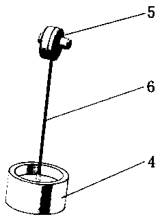
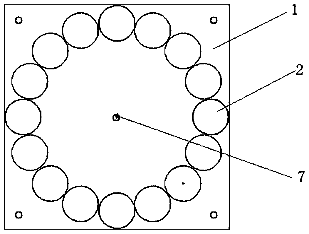
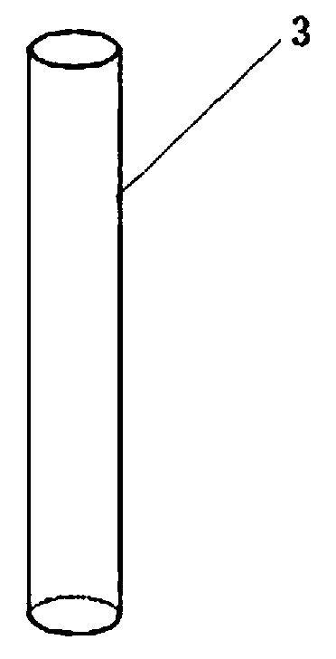
[0043] see Figure 1~3 , shows the denitrification culture device of this embodiment, including a base 1, several straight pipes 3 and a rotating unit. The base 1 is provided with a fixed groove 2 around the center of the base, and the fixed groove 2 is used to place the straight pipe 3 . In this embodiment, the diameter of the straight pipe is 4.7 cm, and the length of the pipe is 29 cm; the number of fixing slots is 16. During use, the fixing slots can be filled or not filled with straight tubes. The bottom opening of the straight pipe 3 is provided with a detachable rubber plug, and the top opening of the straight pipe 3 is provided with a detachable cover 4 with a magnet 5 . Specifically, the magnet 5 is fixedly connected to the inner surface of the cover 4 through a metal wire 6 . The rotating unit includes a rotor, a rotating shaft, and a motor, the rotor is installed in the center of the base,...

Embodiment 2

[0047] This embodiment will provide a kind of denitrification cultivation method utilizing the device of embodiment 1, and the specific steps are as follows:

[0048] In the first step, the soil column is sampled.

[0049]Remove the rubber plug at the bottom of the straight pipe, insert the bottom end of the straight pipe into the original soil column, the soil column is about 6cm deep into the straight pipe, take out the straight pipe and plug the bottom end of the straight pipe with a rubber stopper. In this embodiment, a total of 3 sampling points are collected, 5 soil columns are collected at each sampling point, and 6 soil columns are collected at the last sampling point. After collecting the 16 straight pipes of the soil column, insert them into the fixing grooves on the base in turn, and mark the numbers. Fill the straight pipe with raw water from the top of the straight pipe, cover it, and bring it back to the laboratory for further denitrification cultivation.

[00...


PUM


Abstract

The invention discloses a denitrification culture device and a method for measuring denitrification rate. The denitrification culture device comprises a base, a plurality of straight pipes and a rotating unit, wherein a circle of fixing grooves are formed on the base and around the center of the base; a detachable rubber plug is arranged at a bottom end opening of each straight pipe, and a detachable cover is arranged at a top end opening of each straight pipe; one end of a metal wire is fixed on the inner side of each cover, and the other end of the metal wire is connected with a magnet; whenthe covers cover the top end openings of the straight pipes, the magnets are located in the straight pipes; the rotating unit comprises a rotor, a rotating shaft and a motor, the rotor is detachablyinstalled in the center of the base, the rotating shaft is vertical to the base, and the two ends of the rotating shaft are connected with the rotor and the output end of the motor respectively. A gasflow culture technology and a <15>N isotope tracing technology are combined, so that higher sensitivity of the isotope tracing method is ensured, and tightness of a denitrification culture system anddiffusion of gas are also guaranteed.

Description

technical field [0001] The invention belongs to the technical field of denitrification measurement, and in particular relates to a denitrification cultivation device and a method for measuring denitrification rate. Background technique [0002] The denitrification process is an important part of the nitrogen biogeochemical cycle, and is considered to be one of the most important ways of nitrogen loss and an important means to reduce the environmental nitrogen load. At present, there are three main methods for denitrification determination: [0003] 1) Acetylene inhibition method, based on the fact that high concentrations of acetylene can inhibit nitrification and N 2 O to N 2 reduction, so that N 2 O becomes the final product of denitrification, and the denitrification rate can be calculated indirectly. However, acetylene inhibits nitrification and underestimates the loss of denitrification, thus affecting the accuracy of the determination results. In addition, in clay...

Claims


Application Information

Patent Timeline
IPC IPC(8): G01N27/62C02F3/28C02F101/16
Inventor 卜红梅宋献方刘士平
Owner INST OF GEOGRAPHICAL SCI & NATURAL RESOURCE RES CAS
Why Eureka
Try Eureka