Telescope capable of reducing influence of direct sunlight

A telescope and sunlight technology, applied in the field of telescopes, can solve problems such as unfavorable calculation, reduce the intensity of Ring effect, etc., and achieve the effect of convenient replacement of convex lenses, reduction of influence, and reduction of influence

Pending Publication Date: 2019-06-28
HUAIBEI NORMAL UNIVERSITY
View PDF0 Cites 0 Cited by
  • Summary
  • Abstract
  • Description
  • Claims
  • Application Information

AI Technical Summary

Problems solved by technology

[0008] The object of the present invention is to provide a telescope that reduces the influence of direct sunlight to solve the problem that when the telescope is used to point to the zenith for measurement, the direct light will reduce the intensity of the Ring effect in the measurement spectrum, resulting in lower measurement results than model simulation results , which is not conducive to the problem of subsequent calculations

Method used


Image

  • Telescope capable of reducing influence of direct sunlight
  • Telescope capable of reducing influence of direct sunlight
  • Telescope capable of reducing influence of direct sunlight

Examples


Embodiment 1

[0054] This embodiment proposes a telescope that reduces the influence of direct sunlight, which is used to solve the problem that when the telescope points to the zenith for measurement, the direct light will reduce the intensity of the Ring effect in the measurement spectrum, resulting in a lower measurement result than the model simulation result. Not conducive to the problem of subsequent calculations. The field of view of the telescope is generally fixed at 0.2°. In this embodiment, in order to reduce the influence of direct sunlight on the measurement results, the following two methods are adopted:

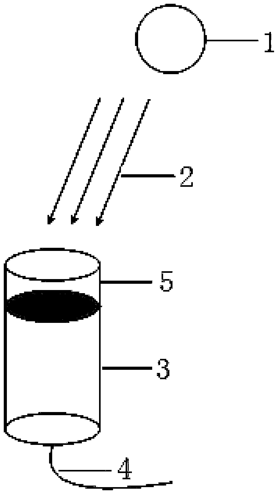
[0055] 1. Reference figure 1 , add an additional lens barrel 2 5 on the lens barrel 3 (the position of the convex lens remains unchanged), that is, the telescope in the present embodiment includes a lens barrel 3, a convex lens (not shown) and a lens barrel 2 5; lens barrel 2 5 is fixed on lens barrel 1 3, and is integrally formed with lens barrel 1 3. Convex lens is insta...

Embodiment 2

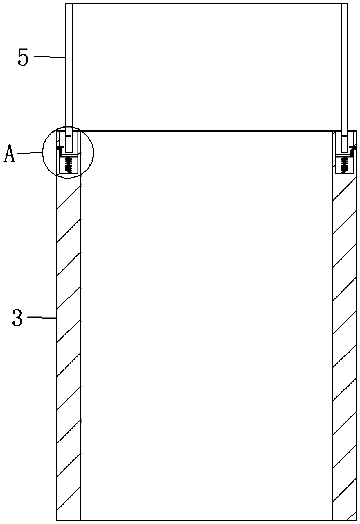
[0060] The difference between this embodiment and embodiment 1 is that the second lens barrel 5 is detachably installed on the first lens barrel 3, so as to achieve the effect of conveniently replacing the convex lens and wiping the convex lens. In this implementation, lens barrel 2 5 can be detachably installed on lens barrel 1 3, and the following improvements are made to lens barrel 1 3 and lens barrel 2 5:

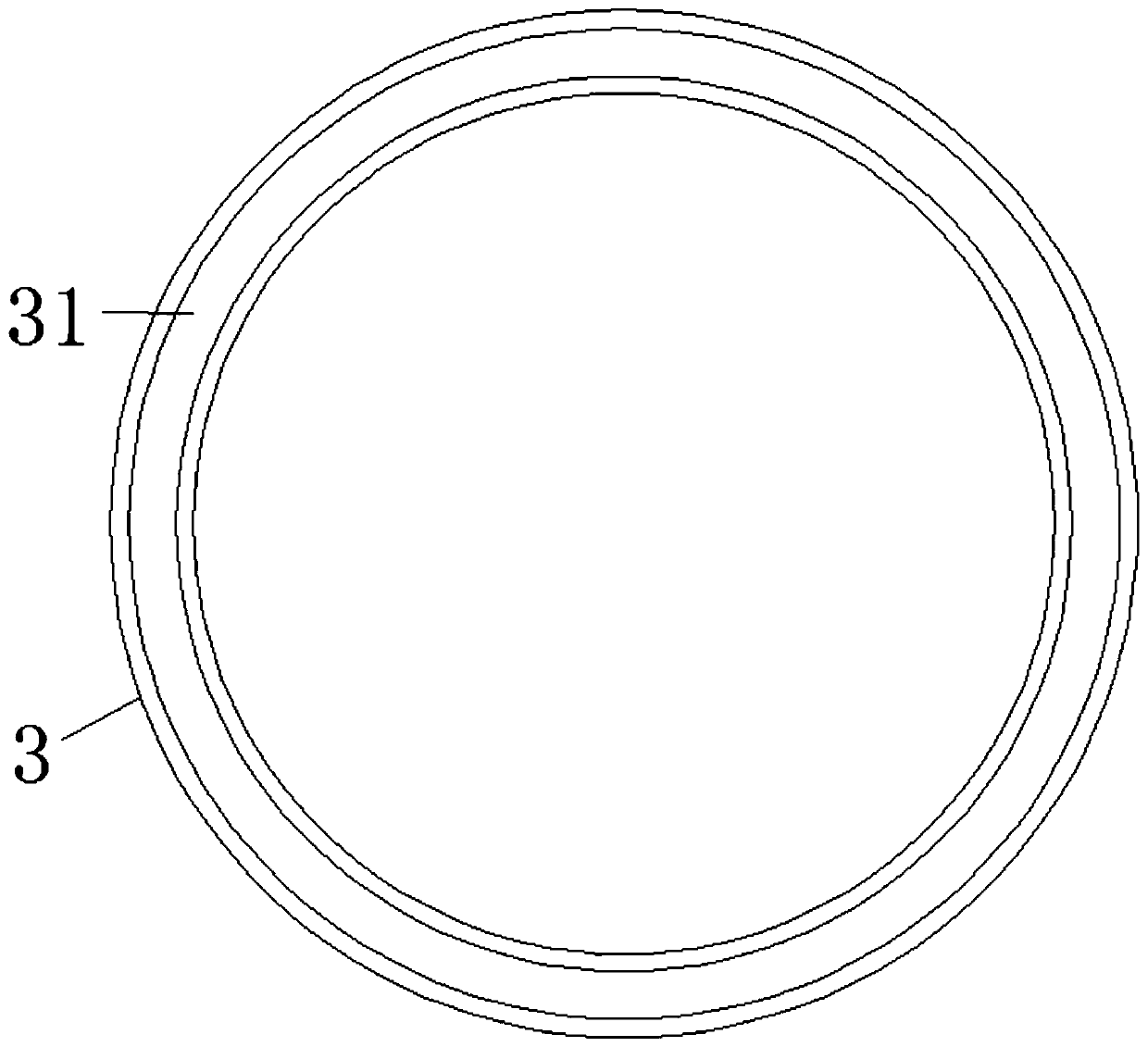
[0061] refer to figure 2 , The end surface of the lens barrel 3 is provided with an annular receiving groove 31 coaxial with the lens barrel 3. refer to Figure 3-4 , A plurality of slots 1 51 are provided on the outer wall of one end of the lens barrel 2 5 . A plurality of slots 1 51 are arranged in a ring on the outer wall of the lens barrel 2 5 . In this embodiment, the number of the slot one 51 can be two.

[0062] Such as image 3 with Figure 4 As shown, in addition to the structure described in Embodiment 1, the telescope in this embodiment also includes ...

Embodiment 3

[0071] In this embodiment, a lens barrel cover 6 is added on the basis of Embodiment 2, so that when the telescope is not in use, a large amount of dust will not fall on the convex lens.

[0072] refer to Image 6 , The lens barrel cover 6 is movably installed on the end of the lens barrel 2 5 away from the slot 1 51, and is used to cover the convex lens. In this embodiment, the inner wall of the end of the second lens barrel 5 away from the first slot 51 is provided with two second slots 52 radially symmetrically along the second lens barrel 5 .

[0073] Such as Image 6 As shown, the lens barrel cover 6 includes a cover plate 61 , two sliding rods 62 , two first connecting rods 64 , two connecting rods 65 , a connecting spring 66 and a baffle 67 .

[0074] Wherein, the cover plate 61 is a hollow structure. And the shape and size of the cross section of the cover plate 61 are equal to the shape and size of the cross section of the lens barrel 25, and a strip hole 63 is off...


PUM


Abstract

The invention discloses a telescope capable of reducing influence of direct sunlight. The telescope comprises a lens cone I, a lens cone II and an installation mechanism, wherein an annular accommodating groove coaxial with the lens cone I is formed in the lens cone I; the lens cone II is detachably mounted on the lens cone I through the installation mechanism, and clamping grooves I are formed inthe outer side wall of one end of the lens cone II. The installation mechanism comprises sliders, support springs, telescopic pipes and clamping structures; the sliders are accommodated in the accommodating groove and form an airtight cavity I with the bottom wall of the accommodating groove; the support springs are accommodated in the cavity I. Two ends of each support spring are mounted betweenthe bottom wall of the accommodating groove and the sliders; each clamping structure comprises a cylinder fixed on the inner side wall of the accommodating groove and a piston. One end of each telescopic pipe penetrates through the corresponding slider to be communicated with the cavity I, and the opposite other end is communicated with the cylinder. The lens cone II is added to the lens cone I,and influence of direct scattered light on measurement by the telescope can be weakened.

Description

technical field [0001] The invention relates to the field of telescopes, in particular to a telescope that reduces the influence of direct sunlight. Background technique [0002] Differential Optical Absorption Spectroscopy (DOAS for short) mainly uses the characteristic absorption of gas molecules in the ultraviolet-visible band to measure qualitatively and quantitatively. Due to the advantages of non-contact, real-time, large-scale, multi-component and detectable unknown substances, DOAS technology has been widely used in environmental monitoring, atmospheric remote sensing and atmospheric chemical reaction mechanism research in recent years due to the advantages of differential absorption spectroscopy. According to the different light sources used in DOAS, it can be divided into two types: active DOAS and passive DOAS. Active DOAS systems use artificial light sources (such as xenon lamps, deuterium lamps, etc., and LED lights) as light sources, and passive DOAS systems u...

Claims


Application Information

Patent Timeline
Patent Type & Authority Applications(China)
IPC IPC(8): G02B23/16
Inventor 牟福生李素文雒静陈浩
Owner HUAIBEI NORMAL UNIVERSITY
Why Eureka
Try Eureka