Device and method for increasing capacity of oil-immersed transformer

An oil-immersed transformer and transformer technology, applied in the field of transformers, can solve the problems of heavy construction and renovation work, long construction period, and complexity, and achieve the effects of less difficult construction, shorter construction period, and lower operating temperature rise

Inactive Publication Date: 2019-06-28
DATANG ENVIRONMENT IND GRP
View PDF4 Cites 2 Cited by
  • Summary
  • Abstract
  • Description
  • Claims
  • Application Information

AI Technical Summary

Problems solved by technology

For existing technical transformation, it is usually more complicated, and appropriate changes to the internal structure of the transformer body, winding modification and other measures, the construction and transformation workload is heavy and complicated
Some parts still need to be returned to the factory for renovation, and the construction period is relatively long

Method used


Image

  • Device and method for increasing capacity of oil-immersed transformer
  • Device and method for increasing capacity of oil-immersed transformer
  • Device and method for increasing capacity of oil-immersed transformer

Examples


Embodiment 1

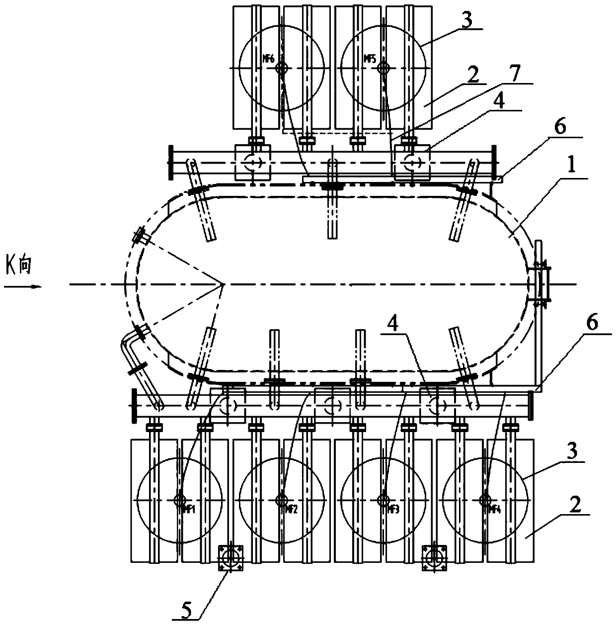
[0033] Example 1, such as figure 1 As shown, a device for increasing the capacity of an oil-immersed transformer according to the embodiment of the present invention includes: a fin radiator 2, a cooling fan 3 and a control box. The chip radiator 2 is installed on the return pipe of the transformer body 1. There are twelve groups of chip radiators 2, among which, eight groups are located on the high voltage side of the transformer body 1, and four groups are located on the low voltage side of the transformer body 1. The cooling fan 3 is installed on the fin radiator 2, and there are six cooling fans 3 in total. Among them, four cooling fans 3 are installed on the fin radiator 2 on the high voltage side of the transformer body 1, and two cooling fans 3 are installed on the transformer body. On the fin radiator 2 on the low-voltage side of the body 1. The control box is located outside the transformer body 1 and connected with the motor of the cooling fan 3 .

[0034] Further,...

Embodiment 2

[0038] Embodiment 2, the present invention also provides a method for increasing the capacity of an oil-immersed transformer, the method comprising the following steps:

[0039] Step 1, install fin radiators 2 on the return pipes on both sides of the oil tank of the transformer body 1. There are twelve groups of fin radiators 2, of which eight groups are located on the high-voltage side of the transformer body 1, and four groups are located on the transformer body 1 low pressure side.

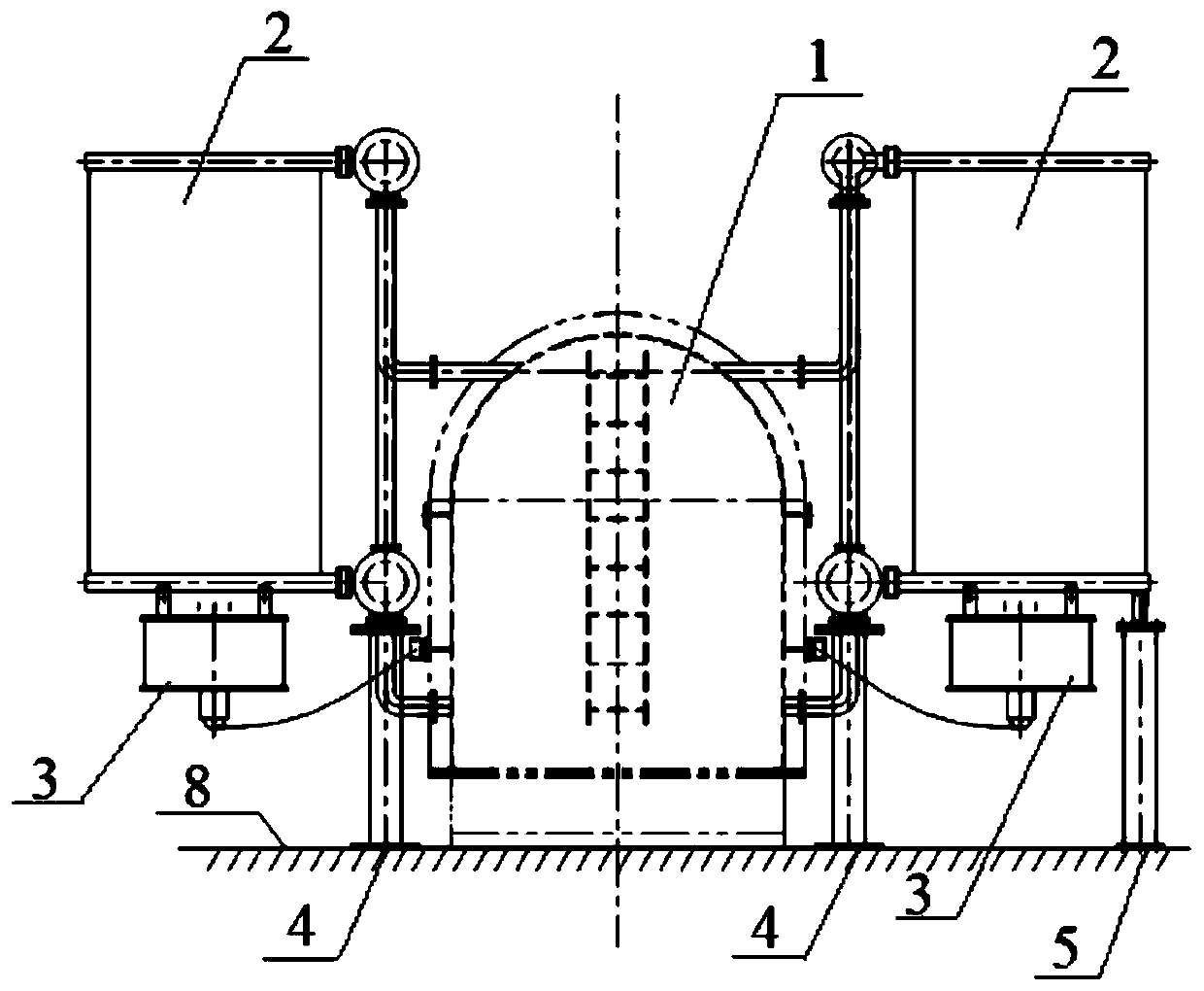
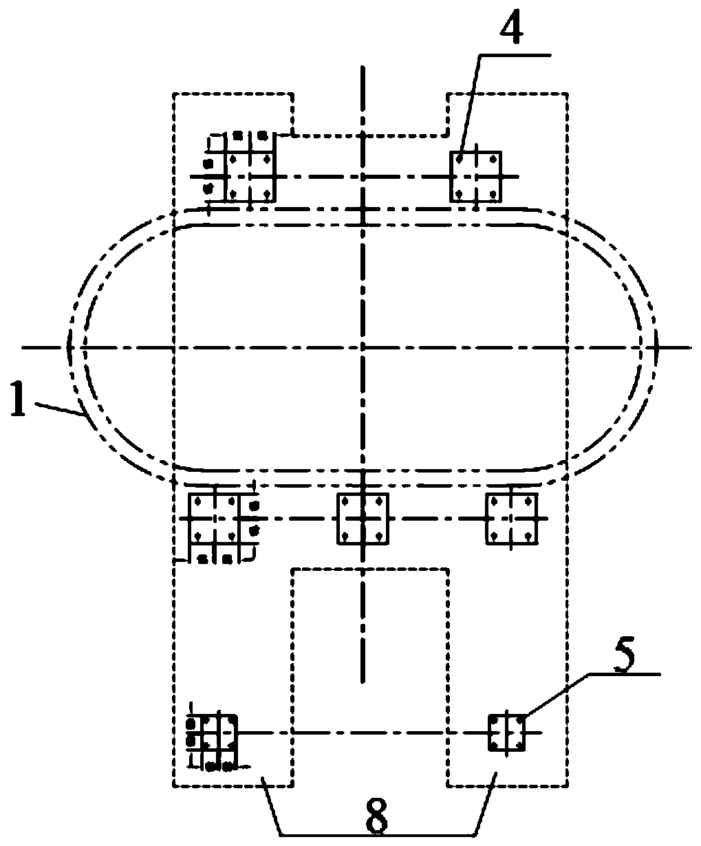
[0040] Step 2, install the return pipes on both sides of the oil tank of the transformer body 1 on the transformer foundation 8 through the bottom plate A4.

[0041] There are five base plates A 4 in total, three of which are located on the high-voltage side of the transformer body 1 and two are located on the low-voltage side of the transformer body 1 . The three bottom plates on the high voltage side of the transformer body 1 are evenly arranged. Each bottom plate A 4 is fixed on the transf...


PUM


Abstract

The invention discloses a device for increasing the capacity of an oil-immersed transformer. The device comprises twelve groups of finned radiators, six cooling fans, and a control box. The finned radiators are arranged on a return pipe of a transformer body. Eight groups of finned radiators are located at the high-voltage side of the transformer body, and four groups of finned radiators are located at the low-voltage side of the transformer body. The cooling fans are arranged on the finned radiators. Four cooling fans are arranged on the finned radiators on the high-voltage side of the transformer body, and two cooling fans are arranged on the finned radiators on the low-voltage side of the transformer body. The control box is positioned outside the transformer body and is connected witha motor of the cooling fans. The invention discloses a method for increasing the capacity of an oil-immersed transformer. The transformer has the beneficial effects that on the premise that the transformer body is kept unchanged, only the cooling system equipment of the transformer body is replaced. Therefore, the capacity increasing requirement of the transformer is met.

Description

technical field [0001] The invention relates to the technical field of transformers, in particular to a device and method for increasing the capacity of an oil-immersed transformer. Background technique [0002] Under normal circumstances, due to the transformation project of the power plant, after some system transformations, the power load of the plant power part has increased compared with the original one. For the original high-voltage plant oil-immersed transformer (hereinafter referred to as the transformer) , The load connected to the transformer means that it needs to be increased, and the original transformer needs to be transformed to increase the capacity. The conventional transformation is to transform the transformer body, such as winding coils and other body accessories, to transform or replace, so that the capacity of the transformer is increased compared with the original transformation, and the purpose of transformer capacity increase is achieved. For the t...

Claims


Application Information

Patent Timeline
Patent Type & Authority Applications(China)
IPC IPC(8): H01F27/12H01F27/08
Inventor 王梅菊何安頔何健
Owner DATANG ENVIRONMENT IND GRP
Why Eureka
Try Eureka