Supercharge Your Innovation With Domain-Expert AI Agents!

HDMI terminal structure and manufacturing method thereof

A technology of HDMI terminal and production method, which is applied in the field of electronic telecommunications, can solve problems such as easy shaking, affecting communication quality, and a large number of mold sets, so as to improve market competitiveness, reduce signal crosstalk, and ensure injection molding quality.

Pending Publication Date: 2019-06-28
东莞市维康汽车电子有限公司
View PDF0 Cites 1 Cited by
  • Summary
  • Abstract
  • Description
  • Claims
  • Application Information

AI Technical Summary

Problems solved by technology

[0005] In the prior art, the HDMI interface (HDMI connector) includes an HDMI terminal structure, and the HDMI terminal structure includes several upper-layer terminals and lower-layer terminals located below the upper-layer terminals. The upper-layer terminals and the lower-layer terminals are generally separated during production. Production, specifically, two sets of molds are used to punch and shape two metal sheets to make upper and lower terminals with different forming structures. The number of mold sets used is large, the cost is high, and the efficiency is not high; There is a production method: use a set of molds to punch and cut the upper layer terminal and the lower layer terminal at the same time on a metal sheet. At that time, only one end of the manufactured upper layer terminal and the lower layer terminal is connected to a strip. The other end of the HDMI interface (HDMI connector) is suspended in the air, and due to the large number of upper and lower terminals in the HDMI interface (HDMI connector), and the smaller size, the other end of the upper and lower terminals is stable and easy to shake, which is inconvenient. The assembly of the entire HDMI interface (HDMI connector), for example, when the terminal is injected into the plastic seat of the HDMI interface (HDMI connector) in the mold, it is not convenient to locate the upper terminal and the lower terminal
In addition, the upper-layer terminals and lower-layer terminals made by the above two manufacturing methods only form two layers of upper and lower layers in the contact part, while the main parts and welding parts of the upper-layer terminals and lower-layer terminals are arranged side by side in a row, so that the upper-layer terminals Most of the structure of the lower terminal is in a row, so that the upper terminal and the lower terminal can only achieve the anti-crosstalk effect in the contact part, but the other parts of the upper terminal and the lower terminal do not have the anti-crosstalk effect, resulting in the upper terminal and the lower terminal. The anti-crosstalk effect between structures is not ideal, which affects the communication quality

Method used


Image

  • HDMI terminal structure and manufacturing method thereof
  • HDMI terminal structure and manufacturing method thereof
  • HDMI terminal structure and manufacturing method thereof

Examples


Embodiment Construction

[0026] The present invention will be further described below in conjunction with specific embodiments and accompanying drawings.

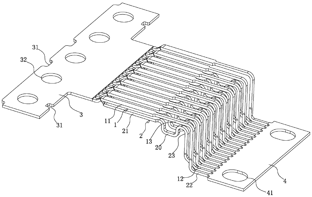
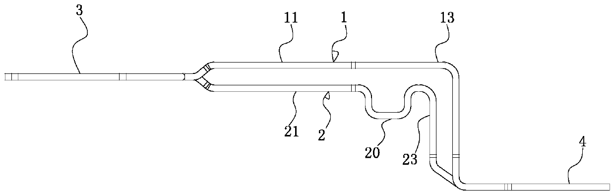
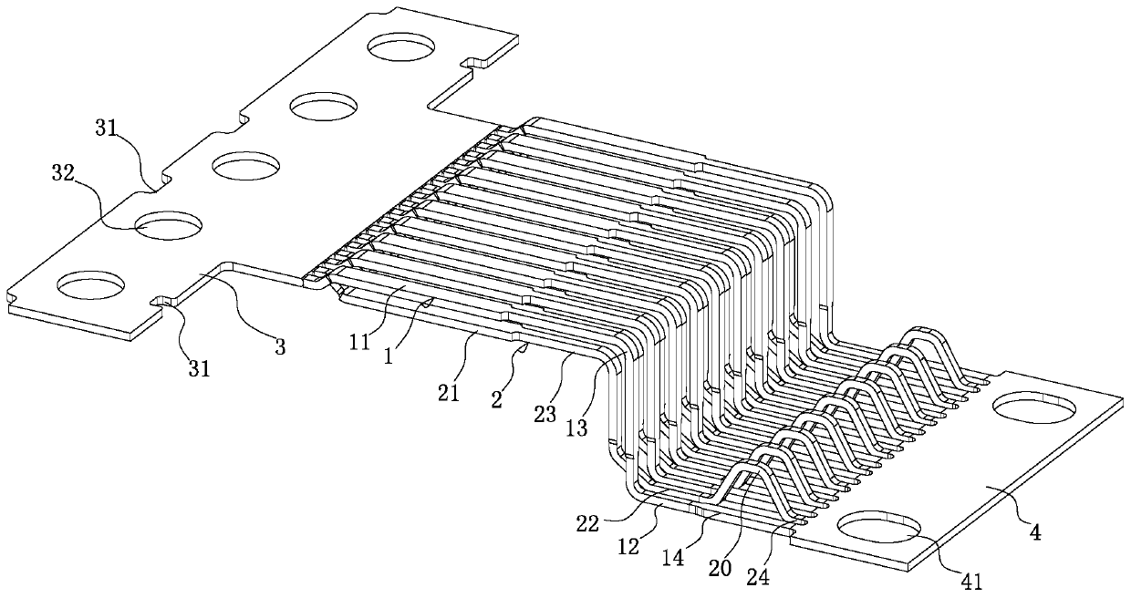
[0027] See Figure 1-4As shown, it is an HDMI terminal structure. The HDMI terminal structure includes a first terminal 1 and a second terminal 2 formed by cutting in half and tearing up and down and distributed in two layers of staggered upper and lower layers, wherein the first terminal 1 It includes a first contact portion 11 that is solidly integrated and sequentially connected, a bent first main body portion 13 and a first solder leg 12; the second terminal 2 includes a second contact portion 21 that is solidly integrated and sequentially connected , the bent second main body portion 23 and the second solder leg 22; the end portion of the first contact portion 11 of the first terminal 1 and the end portion of the second contact portion 21 of the second terminal 2 are uniformly connected to the first The side of the tape 3, and the first conta...


PUM


Abstract

The invention discloses an HDMI terminal structure and a manufacturing method thereof. The HDMI terminal structure comprises a first terminal and a second terminal, wherein the first terminal and thesecond terminal are formed in an up-and-down opposite cutting tearing mode and are distributed in an up-and-down staggered mode. The first terminal comprises a first contact part, a bent first main body part and a first welding pin which are fixed into a whole and sequentially connected. The second terminal comprises a second contact part, a bent second main body part and a second welding pin which are fixed into a whole and are sequentially connected. The end part of the first contact part of the first terminal and the end part of the second contact part of the second terminal are integrallyconnected to the side edge of a first material strap. The first contact part and the first main body part are respectively staggered with the second contact part and the second main body part in an upper-lower manner to form an interval. The first welding pin of the first terminal and the second welding pin of the second terminal are staggered and distributed in a row and are integrally connectedwith the side edge of a second material strip. The second terminal is bent to form an excess material bending part, so that the first terminal and the second terminal are equal in length after being straightened.

Description

Technical field: [0001] The invention relates to the technical field of electronic telecommunication, in particular to an HDMI terminal structure and a manufacturing method thereof. Background technique: [0002] High Definition Multimedia Interface (English: High Definition Multimedia Interface, referred to as) is a fully digital video and sound transmission interface, which can send uncompressed audio and video signals. HDMI can be used in equipment such as set-top boxes, DVD players, personal computers, video game consoles, integrated amplifiers, digital audio and televisions. HDMI can send audio and video signals at the same time. Since the audio and video signals use the same wire, it greatly simplifies the installation difficulty of the system line. [0003] HDMI is designed to replace older analog signal audio and video transmission interfaces such as SCART or RCA terminals. It supports all types of TV and computer video formats, including SDTV, HDTV video images, p...

Claims


Application Information

Patent Timeline
Patent Type & Authority Applications(China)
IPC IPC(8): H01R13/02H01R13/6461H01R43/16H01R43/24
Inventor 唐付君
Owner 东莞市维康汽车电子有限公司
Features
  • R&D
  • Intellectual Property
  • Life Sciences
  • Materials
  • Tech Scout
  • Unparalleled Data Quality
  • Higher Quality Content
  • 60% Fewer Hallucinations
Learn More