Flash detection control device, electronic equipment comprising same and system

A technology for detection and control and electrical equipment, applied in the field of smart home, can solve problems such as the failure of smart switch circuits, intermittent flickering of lamps, and network abnormalities

Pending Publication Date: 2019-06-28
QINGDAO YEELINK INFORMATION TECH
View PDF0 Cites 5 Cited by
  • Summary
  • Abstract
  • Description
  • Claims
  • Application Information

AI Technical Summary

Problems solved by technology

For example, the existing smart switch generally needs a separate fire wire, and if the traditional circuit wiring is rewired, it will bring great inconvenience. Therefore, a single fire power-taking technology without rewiring has been developed.
In the existing single-fire power supply, the single-fire smart switch needs to be connected to the power grid after being connected to the lamp in series. In this way, the smart switch circuit cannot work when the current is small, and the intermittent flickering of the lamp will be caused when the current is too large.
[0005] 2...

Method used


Image

  • Flash detection control device, electronic equipment comprising same and system
  • Flash detection control device, electronic equipment comprising same and system
  • Flash detection control device, electronic equipment comprising same and system

Examples


Embodiment 1

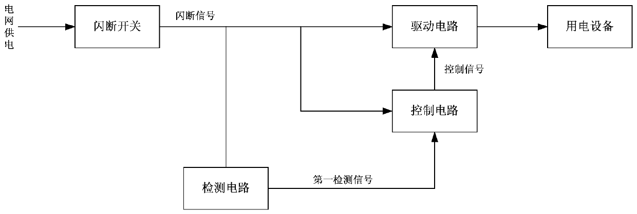
[0065] Such as figure 1 As shown, this embodiment provides a flicker detection control device, which is applied to the power supply circuit of electrical equipment, including a detection circuit, a control circuit and a drive circuit. The detection circuit is used to detect the flicker signal in the power supply circuit and generate a detection signal, the control circuit is used to receive the detection signal and the external wireless control signal, and based on the detection signal or the external wireless control signal, control the state transition of the electric device through the drive circuit.

[0066] Specifically, the flash detection control device includes a detection circuit, a control circuit and a drive circuit. Generate a flash signal when the power supply circuit flashes, and the detection circuit detects the flash signal and generates a first detection signal; the control circuit receives and judges whether the flash signal is the first flash signal based on...

Embodiment 2

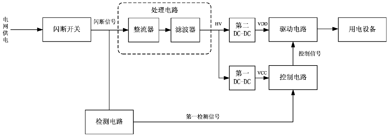
[0084] Such as image 3 As shown, this embodiment provides a flicker detection and control device. The difference between the flicker detection and control device and Embodiment 1 is that the flicker detection device in this embodiment further includes a processing circuit.

[0085] In the embodiment of the present application, the processing circuit includes a rectifier connected in series with the flash switch, a filter, a first DC-DC converter, and a second DC-DC converter connected in parallel with the first DC-DC converter, wherein the processing The circuit is electrically connected to the control circuit through the first DC-DC converter; and the processing circuit is electrically connected to the driving circuit through the second DC-DC converter.

[0086] In the embodiment of the present application, the input end of the processing circuit is connected to the output end of the flash switch, the output end is connected to the control circuit through the first DC-DC conve...

Embodiment 3

[0095] Such as Figure 5 As shown, the detection circuit includes a first resistor R1 and a second resistor R2, wherein the first end of R1 of the first resistor is electrically connected to the output end of the first DC-DC converter, and its voltage is VDD or HV, and the first resistor R1 The second terminal of the second resistor R2 is connected to the first terminal of the second resistor R2 for generating the first detection signal ADC1 and feeding it to the control circuit, and the second terminal of the second resistor R2 is grounded to GND.

[0096] The control circuit includes a first micro-control unit MCU. When the first MCU judges that the voltage value of the first detection signal drops first and then rises within the first predetermined time, the first MCU judges that the flash signal is the first flash signal, and generates the first flash signal. A control signal drives the electrical equipment to change from the first state to the second state.

[0097] The ...


PUM

PropertyMeasurementUnit
Capacitanceaaaaaaaaaa

Abstract

The invention discloses a flash detection control device. The device is applied to a power supply circuit of electric equipment. The device comprises a detection circuit, a control circuit and a driving circuit. The detection circuit is used for detecting a flash signal in the power supply circuit and generating a detection signal. The control circuit is used for receiving the detection signal andan external wireless control signal and controlling the state transition of electric equipment through the driving circuit based on the detection signal or the external wireless control signal. The invention further discloses electronic equipment and a system comprising the device. According to the invention, the electric equipment is controlled by detecting the flash signal. Meanwhile, the powersupply of the wireless control circuit is not influenced at all. The control of the electric equipment by an entity switch and a wireless signal is realized at the same time.

Description

technical field [0001] The present application relates to the field of smart home technology, in particular to a flash detection control device, electronic equipment and systems including the same. Background technique [0002] Smart home is based on the residence as a platform, using integrated wiring technology, network communication technology, security technology, automatic control technology, audio and video technology to integrate the facilities related to home life, build an efficient management system for residential facilities and family schedules, and improve Home safety, convenience, comfort, artistry, and to achieve an environmentally friendly and energy-saving living environment. Generally speaking, smart home is based on the premise of home automation, that is, the use of micro-processing electronic technology to integrate or control electronic and electrical products or systems in the home, such as: plug boards, lighting, audio, coffee stoves, computer equipme...

Claims


Application Information

Patent Timeline
IPC IPC(8): H05B33/08H05B44/00
CPCY02B20/30
Inventor 姜兆宁刘达平魏巍孙胜利郭宗渗刘飞韩猛
Owner QINGDAO YEELINK INFORMATION TECH
Why Eureka
Try Eureka