Automatic paint spraying equipment

An automatic painting and equipment technology, applied in the direction of metal processing equipment, grinding/polishing equipment, spraying device, etc., can solve the problems of high production cost and complex structure, and achieve low production cost, high degree of automation and fast polishing speed Effect

Inactive Publication Date: 2019-07-02
天津双合盛自行车有限公司
View PDF6 Cites 2 Cited by
  • Summary
  • Abstract
  • Description
  • Claims
  • Application Information

AI Technical Summary

Problems solved by technology

At present, the structure of the painting equipment used on the market is relatively complicated, and the production cost is relatively high

Method used


Image

  • Automatic paint spraying equipment
  • Automatic paint spraying equipment

Examples


Embodiment

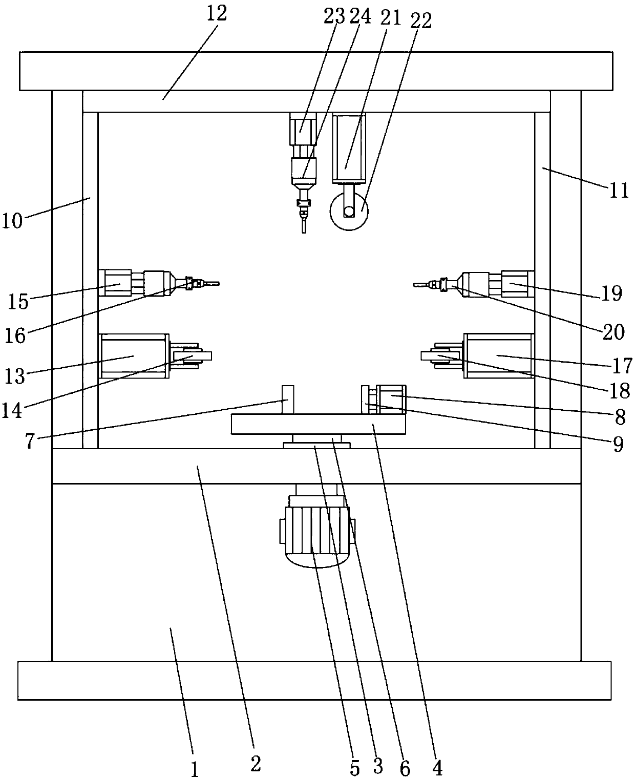
[0019] Such as figure 1 As shown, an automatic painting equipment includes a frame 1, a frame table 2, a bearing 3, a rotating seat 4, a motor 5, a rotating shaft 6, a limit plate 7, a clamping plate cylinder 8, a clamping plate 9, a first Side sliding rail 10, second side sliding rail 11, upper sliding rail 12, first side buffing wheel cylinder 13, first side buffing wheel 14, first side paint gun cylinder 15, first side paint gun 16, second side Polishing wheel cylinder 17, second side polishing wheel 18, second side paint spray gun cylinder 19, second side paint spray gun 20, upper polishing wheel cylinder 21, upper polishing wheel 22, upper paint spray gun cylinder 23, upper paint spray gun 24, machine The stand 2 is fixed in the middle of the frame 1, the bearing 3 is fixed on the stand 2, the swivel seat 4 is located above the stand 2, the motor 5 is installed on the stand 1 and is located below the stand 2, The rotating shaft 6 is installed in the bearing 3, one end of...


PUM


Abstract

The invention belongs to the field of air compressor production equipment and particularly relates to automatic paint spraying equipment. The automatic paint spraying equipment is characterized in that a motor is located below a machine frame table; one end of a rotary shaft is connected with the motor and the other end of the rotary shaft is connected with a rotary seat; a limiting plate is fixedto the position above the rotary seat; a clamping plate air cylinder is connected with a clamping plate; a first lateral polishing wheel air cylinder is connected with a first lateral polishing wheel; a first lateral paint spraying gun air cylinder is connected with a first lateral paint spraying gun; a second lateral polishing wheel air cylinder is connected with a second lateral polishing wheel; a second lateral paint spraying gun air cylinder is connected with a second lateral paint spraying gun; an upper polishing wheel air cylinder and an upper paint spraying gun air cylinder are mountedon an upper sliding guide rail; the upper polishing wheel air cylinder is connected with an upper polishing wheel; the upper paint spraying gun air cylinder is connected with an upper paint sprayinggun; and the upper polishing wheel and the upper paint spraying gun are located above the rotary seat.

Description

technical field [0001] The invention belongs to the field of air compressor production equipment, in particular to an automatic painting equipment. Background technique [0002] Air compressor is the basic product of industrial modernization. It is often said that electricity and automation have the meaning of full pneumatic, and air compressor is to provide air source power. It is the core equipment of the pneumatic system and the main body of the electromechanical air source device. A device that converts the mechanical energy of the prime mover into gas pressure energy is a pneumatic generator that compresses air. After the casing in the air compressor is processed, the surface of the casing needs to be polished with a polishing wheel, and then the painting operation is carried out after the polishing is completed. At present, the structure of the painting equipment used on the market is relatively complicated, and the production cost is relatively high. Contents of th...

Claims


Application Information

Patent Timeline
Patent Type & Authority Applications(China)
IPC IPC(8): B24B1/00B24B19/00B05B13/02B05B13/04
CPCB05B13/0228B05B13/0278B05B13/04B24B1/00B24B19/00
Inventor 张加冉
Owner 天津双合盛自行车有限公司
Why Eureka
Try Eureka