Intelligent communication controlled power station boiler waste heat utilization system

A power station boiler and waste heat technology, applied in the direction of combustion control, indirect heat exchanger, lighting and heating equipment, etc., can solve the problems of heat exchange capacity decline, affect heat exchange efficiency, lack of intelligent control, etc., to achieve suppression of backflow, Promotes smooth flow and full utilization

Inactive Publication Date: 2019-07-02
XUCHANG LONGGANG POWER GENERATION
View PDF10 Cites 4 Cited by
  • Summary
  • Abstract
  • Description
  • Claims
  • Application Information

AI Technical Summary

Problems solved by technology

During the evaporation process of the heat pipe, it will inevitably carry liquid to the steam end. At the same time, because of the exothermic condensation of the condensation end, there will be liquid in the condensation end, and the liquid will inevitably mix with the steam, so that the fluid in the heat pipe is vapor. Liquid mixture, the existence of vapor-liquid mixture causes the gas to mix together, and the heat exchange capacity between the liquid and the liquid decreases, which greatly affects the heat exchange efficiency
[0005] In the boiler waste heat utilization system of the prior art, there is a lack of research on intelligent control, especially the intelligent control when there are multiple waste heat utilization equipment at the same time, such as setting heat distribution, etc.

Method used


Image

  • Intelligent communication controlled power station boiler waste heat utilization system
  • Intelligent communication controlled power station boiler waste heat utilization system
  • Intelligent communication controlled power station boiler waste heat utilization system

Examples


Embodiment Construction

[0042] The specific embodiments of the present invention will be described in detail below in conjunction with the accompanying drawings.

[0043] In this article, if there is no special explanation, when it comes to formulas, " / " means division, and "×" and "*" mean multiplication.

[0044]The specific embodiments of the present invention will be described in detail below in conjunction with the accompanying drawings.

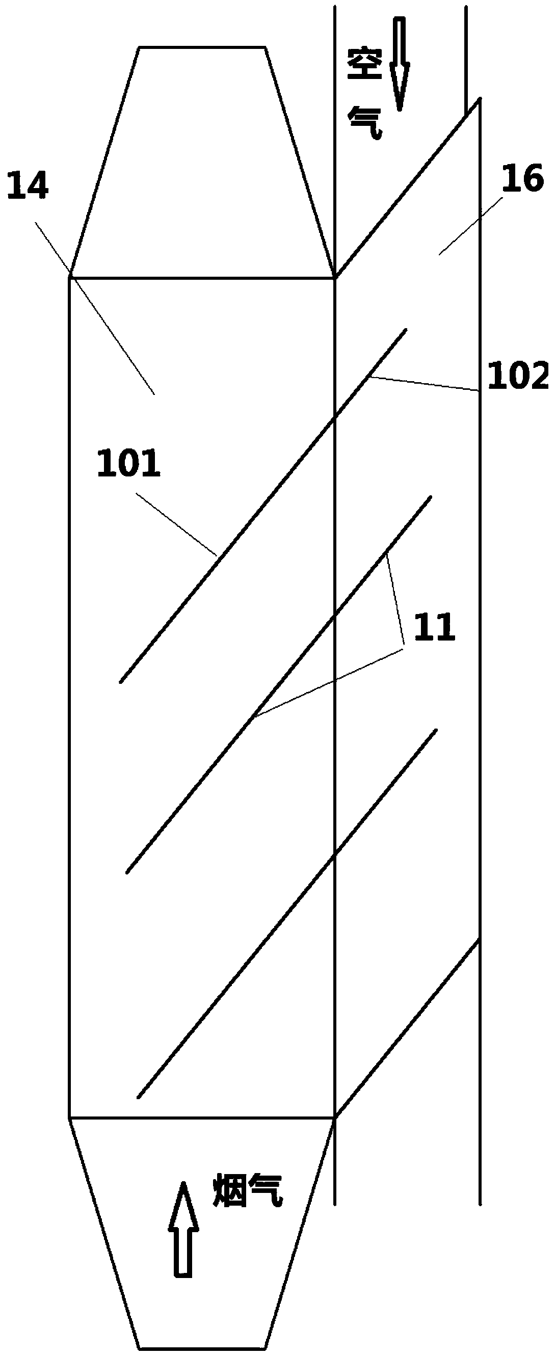
[0045] A utility boiler flue gas waste heat utilization system, the waste heat utilization system includes an air preheater 1, the air preheater 1 includes a heat pipe 10, a flue gas channel 14 and an air channel 16, and the heat pipe 10 includes an evaporation The condensing end 101 and the condensing end 102, the condensing end 102 is arranged in the air passage 12, and the evaporating end 101 is arranged in the flue. The evaporating end 101 absorbs the waste heat of the flue gas in the boiler flue, and transfers the heat to the air in the air channel 12 th...


PUM


Abstract

The invention provides an intelligent communication controlled power station boiler waste heat utilization system which comprises an air preheater and a heat reservoir. The system comprises an upstream valve and a downstream valve. The upstream valve is arranged on an upstream flue of the air preheater and the heat reservoir, and the downstream valve is arranged on a downstream flue of the air preheater and the heat reservoir. The system also comprises a central controller which controls on-off of the upstream valve and the downstream valve according to data detected by a flue sensor. According to the system, on-off of the valves is controlled intelligently according to the flue gas flow, so that a closed loop circulating function between the heat reservoir and the air preheater is achieved according to the actual condition. Under the circumstance of no flue gas waste heat, the air preheater is heated by means of heat stored by the flue gas waste heat to meet the actual working demandof the air preheater, so that the flue gas waste heat can be utilized fully, and excessive heat waste is avoided.

Description

technical field [0001] The present invention is a part of the subject project jointly developed with the enterprise, is an improvement on the previous application, relates to the field of waste heat recovery of heat pipes, and particularly relates to a method and device for recovering waste heat of flue gas by using heat pipes. Background technique [0002] With the rapid development of my country's economy, energy consumption is increasing day by day, and the problem of deteriorating urban air quality is becoming more and more prominent. It is urgent to save energy and reduce the emission of harmful environmental substances. In the common steam generation process, one of the main reasons for high energy consumption and serious pollution is that the exhaust temperature of boiler flue gas is too high, which wastes a lot of energy. Therefore, the waste heat of boiler exhaust gas is recovered and reused to achieve energy saving and emission reduction. purpose, while protecting ...

Claims


Application Information

Patent Timeline
Patent Type & Authority Applications(China)
IPC IPC(8): F23L15/04F23N3/06F28D15/04F28D21/00
CPCF23L15/04F23L2900/15043F23N3/06F23N2900/05005F28D15/046F28D21/001Y02E20/34
Inventor 王逸隆马军江程李言伟连根款
Owner XUCHANG LONGGANG POWER GENERATION
Why Eureka
Try Eureka