System and method for azimuth element and distortion testing of optical remote sensor

An optical remote sensor and internal orientation element technology, which is used in optical instrument testing, machine/structural component testing, and optical performance testing, etc. It can solve problems such as low efficiency, huge demand for testing equipment, and untimely test results.

Active Publication Date: 2019-07-02
BEIJING RES INST OF SPATIAL MECHANICAL & ELECTRICAL TECH
View PDF6 Cites 3 Cited by
  • Summary
  • Abstract
  • Description
  • Claims
  • Application Information

AI Technical Summary

Problems solved by technology

[0011] The technical solution problem of the present invention is: to overcome the deficiencies of the prior art, provide a kind of azimuth element and distortion test system and method in the optical remote sensor, solve the large-scale requirement of the existing test equipment, long test time and low efficiency and test results untimely problem

Method used


Image

  • System and method for azimuth element and distortion testing of optical remote sensor
  • System and method for azimuth element and distortion testing of optical remote sensor
  • System and method for azimuth element and distortion testing of optical remote sensor

Examples


Embodiment Construction

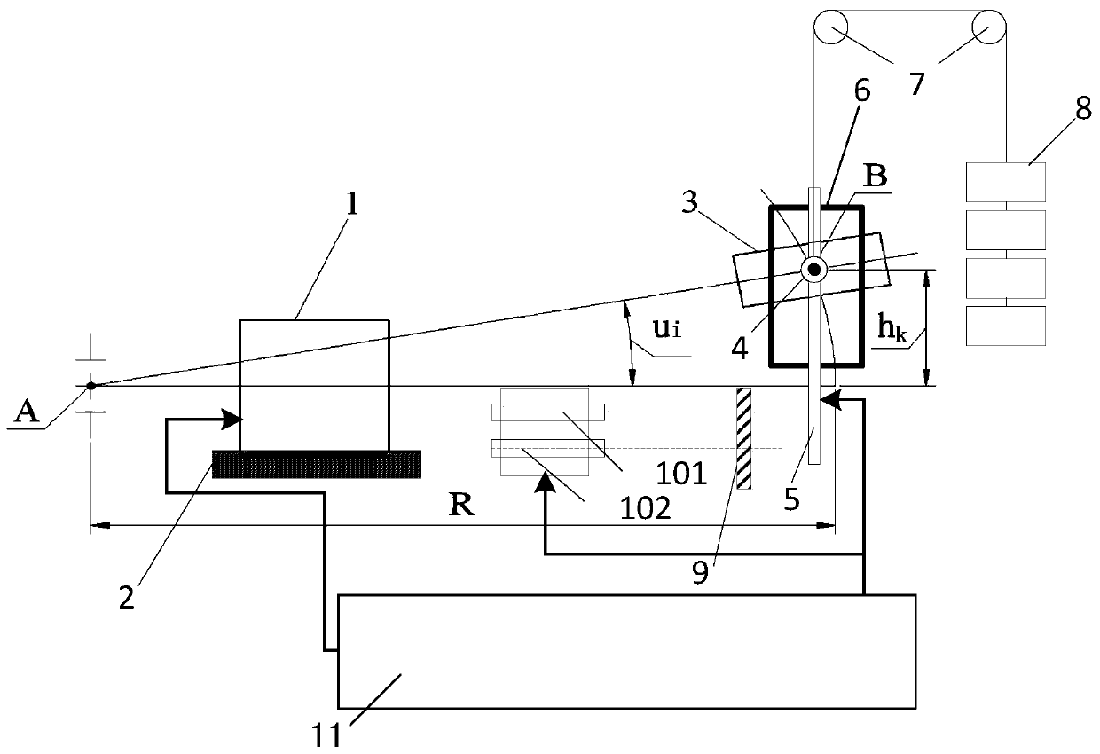
[0064] An optical remote sensor internal orientation element and distortion test system of the present invention is attached figure 2 As shown, it includes: test platform 2, collimator 3, rotating mechanism, slider 4, guide rail 5, motion support 6, fixed pulley 7, counterweight 8, plane mirror 9, first photoelectric autocollimator 101 , a second photoelectric autocollimator 102 , and a data processing system 11 . The optical remote sensor 11 to be tested is placed on the test platform 2, and the direction of its line array CCD is adjusted to be perpendicular to the earth by optical means. The collimator 3 simulates parallel light at infinity, and projects the reticle at the focal plane of the collimator onto the focal plane of the camera under test. The collimator 3 is connected with the counterweight 8 through the fixed pulley 7 to realize the weight balance of the collimator system and generate a collimated light source injected into the optical remote sensor 1 to be test...


PUM


Abstract

The invention relates to a system and method for azimuth element and distortion testing of an optical remote sensor. The system comprises a collimator, a photoelectric autocollimator, a test platform,and a data processing system. The data processing system determines n sets of test data according to a field angle of a to-be-tested optical remote sensor and determines an inner azimuth element of the to-be-tested optical remote sensor and camera distortion of the to-be-tested optical remote sensor according to an angular offset, obtained by testing by the photoelectric autocollimator, of the optical axis of the collimator and an imaging position of a collimator dividing plate at the to-be-tested optical remote sensor detector. The test platform changes the position of the collimator according to the test data, so that the included angle between the optical axis of the collimator and the optical axis of the to-be-tested optical remote sensor is equal to a testing rotation angle and the vertical distance between the center of the collimator objective lens and the optical axis of the to-be-tested optical remote sensor is equal to the test height corresponding to the testing rotation angle. Therefore, a problem that the traditional inner azimuth element testing device is not suitable for the long-focal-length wide-amplitude optical remote sensor having the entrance pupil position away from the lens is solved.

Description

technical field [0001] The invention relates to a system and method for testing an orientation element and distortion in an optical remote sensor, and belongs to the field of optical remote sensor testing. Background technique [0002] In order to make the image information accurately describe the precise position of space objects, it is necessary to precisely calibrate the inner orientation elements of the optical remote sensor. The high-precision test of the inner orientation elements can provide a guarantee for the satellite's drawing and positioning accuracy. At present, the azimuth elements in the optical remote sensor are calibrated by precise angle measurement method. The schematic diagram of the calibration method is as follows: image 3 Shown: N′ is the rear node of the objective lens of the camera under test, O is the center of the image plane, P is the position of the principal point of the image plane, p is the distance between the principal point P of the image p...

Claims


Application Information

Patent Timeline
Patent Type & Authority Applications(China)
IPC IPC(8): G01M11/02
CPCG01M11/0257
Inventor 王东杰郑君李重阳马丽娜焦文春赵英龙贾馨岳丽清刘君航王静怡
Owner BEIJING RES INST OF SPATIAL MECHANICAL & ELECTRICAL TECH
Why Eureka
Try Eureka