
In-situ soil leaching monitoring test device and method

A test device and test method technology, applied in the direction of measuring device, soil material testing, sampling device, etc., can solve the problems that the time calibration and quantitative collection of leached samples cannot be realized, and achieve long-term automatic monitoring, avoid long-term contact, structure cleverly designed effects

Active Publication Date: 2019-07-02
INST OF HYDROGEOLOGY & ENVIRONMENTAL GEOLOGY CHINESE ACAD OF GEOLOGICAL SCI
View PDF16 Cites 5 Cited by
  • Summary
  • Abstract
  • Description
  • Claims
  • Application Information

AI Technical Summary

Problems solved by technology

[0004] One of the purposes of the present invention is to provide an in-situ monitoring test device for soil leaching, to solve the problem that existing devices cannot realize time calibration and quantitative collection of leaching samples under conditions of field irrigation or rainfall infiltration

Method used


Image

  • In-situ soil leaching monitoring test device and method
  • In-situ soil leaching monitoring test device and method
  • In-situ soil leaching monitoring test device and method

Examples


Embodiment 1

[0033] Example 1: In-situ monitoring test device for soil leaching.

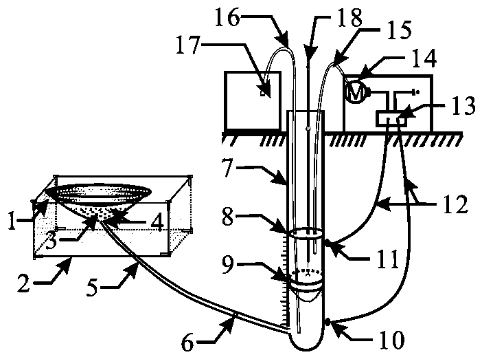
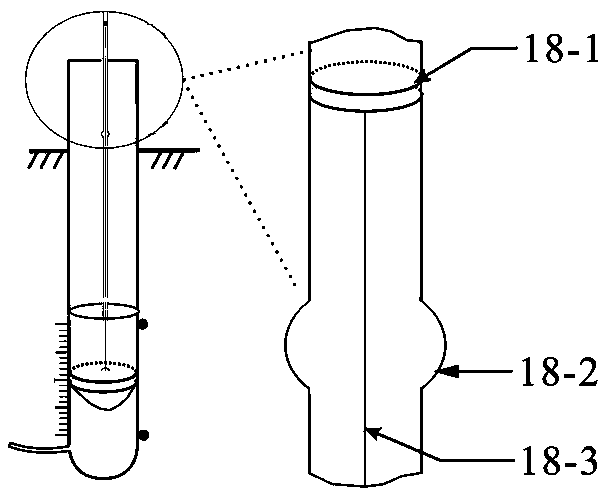
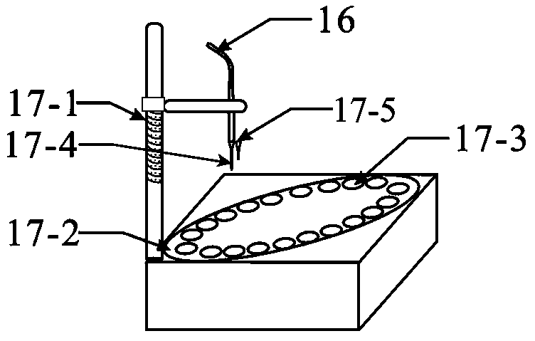
[0034] The device of the present invention mainly includes a receiving tray 1, a liquid reservoir, an exhaust pipe 18, a sampling device 17, an inflation device, a time recorder, a controller 13 and the like.

[0035] The receiving tray 1 is used to receive the soil leachate and perform preliminary filtration on it. The receiving tray 1 includes a funnel-shaped tray body, a filter plate arranged at the mouth of the tray, two layers of nylon gauze 4 arranged below the filter plate, and a quartz sand layer 3 arranged between the two layers of nylon gauze 4 . The plate body of the filter plate is sunken toward the bottom of the disc body, the nylon gauze 4 is a 100-mesh nylon gauze, and the particle size of the quartz sand in the quartz sand layer 3 is 40-60 mesh. The filter plate, the gauze 4 and the quartz sand layer 3 jointly constitute a filter layer, which plays a role in preliminary filtration of the lea...

Embodiment 2

[0061] Example 2: In situ monitoring test method of soil leaching.

[0062] The in-situ monitoring test method of soil leaching of the present invention comprises the steps:

[0063] 1) In the selected test site, excavate the soil, form a pit, and stack the excavated soil in layers for backfilling in layers; Excavate horizontally to form a cuboid cavity. Place a hollow three-dimensional net bracket in the hole. The bracket has four-corner height adjustment screws, horizontal and lateral positioning adjustment screws. Adjust the size and position of the bracket according to actual needs, so that the bracket can play a role in the soil above the hole. A certain supporting role. The receiving tray is placed on the bracket in the hole, and the receiving tray is used to receive the soil drench solution and perform preliminary filtration on it.

[0064] 2) Put the liquid reservoir in the pit, so that the top of the liquid storage cylinder protrudes from the ground, and the liquid...


PUM

PropertyMeasurementUnit
porosityaaaaaaaaaa

Abstract

The invention relates to an in-situ soil leaching monitoring test device and method. The device comprises a receiving disc for receiving leaching liquid, a liquid reservoir communicated with the bottom of the receiving disc, a sampling device communicated with the bottom of the liquid reservoir, an air charging system for filling the reservoir with air, an exhaust pipe for discharging the air in the reservoir, a time recorder, and a controller for controlling the air charging system and the sampling device. According to the invention, in-situ leaching monitoring under the condition of field irrigation or rainfall infiltration is realized; with the specific reservoir storage capacity and sampling bottle volume, the quantitative collection and time calibration of the leaching sample are realized; the concentration process curve of the leaching solution can be obtained; and the kinetic study need of the leaching solution index is met. Moreover, the automation degree is high; and the long-term automatic monitoring need is met.

Description

technical field [0001] The invention relates to a soil detection test device and method, in particular to an in-situ monitoring test device and method for soil leaching. Background technique [0002] Soil is the basic element of terrestrial ecosystems and the material basis for human survival. Soil environmental conditions are directly related to ecological security and agricultural product safety. Soil solution is the general term for water in soil and its solutes, mainly including inorganic ions, organic ions and polymer ions. The soil solution is in close contact with the solid phase, and maintains a dynamic balance with the solid phase surface. Under the conditions of irrigation and rainfall infiltration for a period of time, the research on the change process of the solute composition and concentration in the soil solution has important implications for agricultural irrigation and drainage, pollution control and Improvement of land conditions, etc. have a guiding role....

Claims


Application Information

Patent Timeline
Patent Type & Authority Applications(China)
IPC IPC(8): G01N33/24G01N1/14
CPCG01N1/14G01N33/24G01N2001/1463
Inventor 黄爽兵顾文龙雷珊苏炤新岳钧
Owner INST OF HYDROGEOLOGY & ENVIRONMENTAL GEOLOGY CHINESE ACAD OF GEOLOGICAL SCI
Learn More