Nested mounting structure of Satcom-on-the-move satellite antenna

A technology of satellite antenna and installation structure, which is applied to antenna supports/installation devices, antennas, antennas suitable for movable objects, etc., to achieve the effects of easy conformality, high reliability and compact structure

Inactive Publication Date: 2019-07-02
苏州灵致科技有限公司
View PDF0 Cites 4 Cited by
  • Summary
  • Abstract
  • Description
  • Claims
  • Application Information

AI Technical Summary

Problems solved by technology

[0003] The technical problem to be solved by the present invention is to provide a nested installation structure of the satellite antenna in motion. One or less, to ensure the maximum effective use of space; at the same time, the mobile communication satellite antenna installed based on the nested installation structure can effectively reduce wind resistance, save energy consumption, and greatly alleviate the problems of heat generation and high energy consumption ;It has the characteristics of simple structure, small size, light weight, easy conformal shape, easy concealment, easy installation and high reliability

Method used


Image

  • Nested mounting structure of Satcom-on-the-move satellite antenna
  • Nested mounting structure of Satcom-on-the-move satellite antenna
  • Nested mounting structure of Satcom-on-the-move satellite antenna

Examples


Embodiment 1

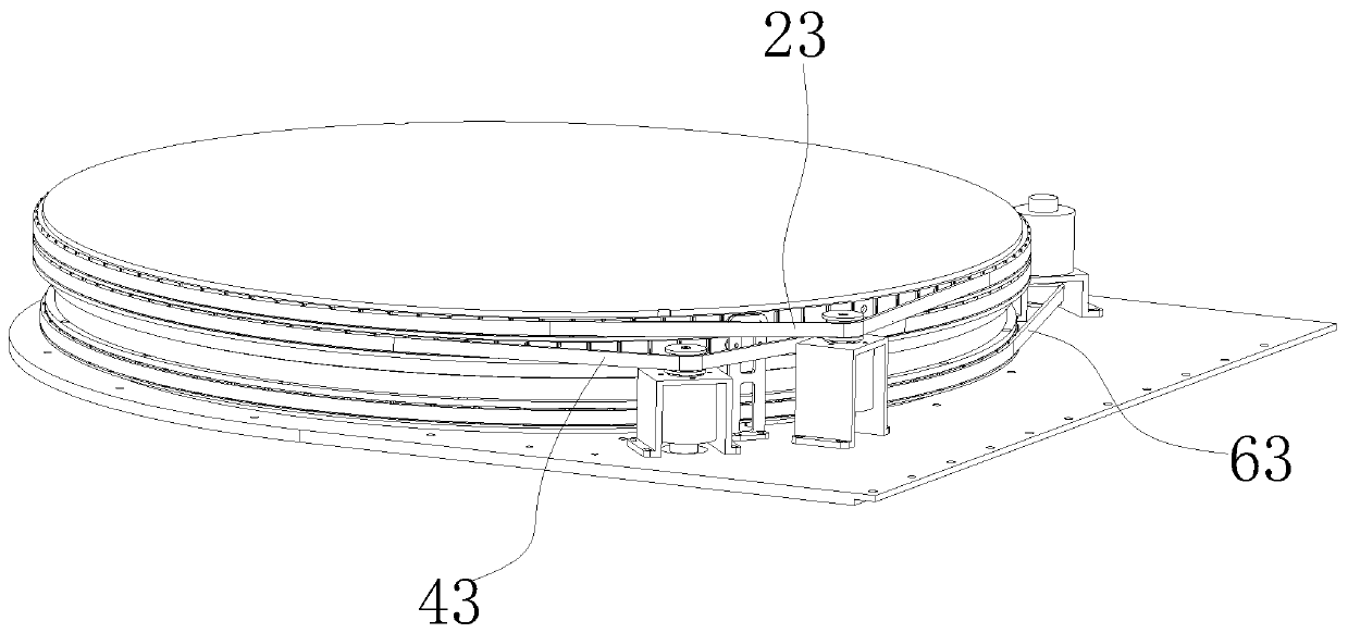
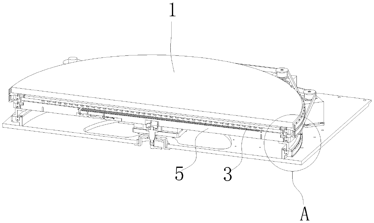
[0033] The invention discloses a nested installation structure of a satellite antenna in motion. The satellite antenna in motion has a polarization disk 1, a pitch disk 3 and an azimuth disk 5 which are sequentially installed in the axial direction. Here, the polarization disk 1 The hubs of the pitch disc 3 and the azimuth disc 5 are located on the same axis. The above-mentioned satellite antenna in motion is coaxially installed with the polarized disk 1, the pitch disk 3 and the azimuth disk 5 through optimized structural design, and installed layer by layer along the vertical direction. In the actual use process, the azimuth disk 5 rotates to realize the azimuth plane The rotation of the pitch disk 3 realizes the beam scanning of the elevation plane, and the rotation of the polarization disk 1 realizes the beam scanning of the polarization angle. In this way, by controlling the independent rotation of the three disks, the antenna can always be aligned with the satellite. The...

Embodiment 2

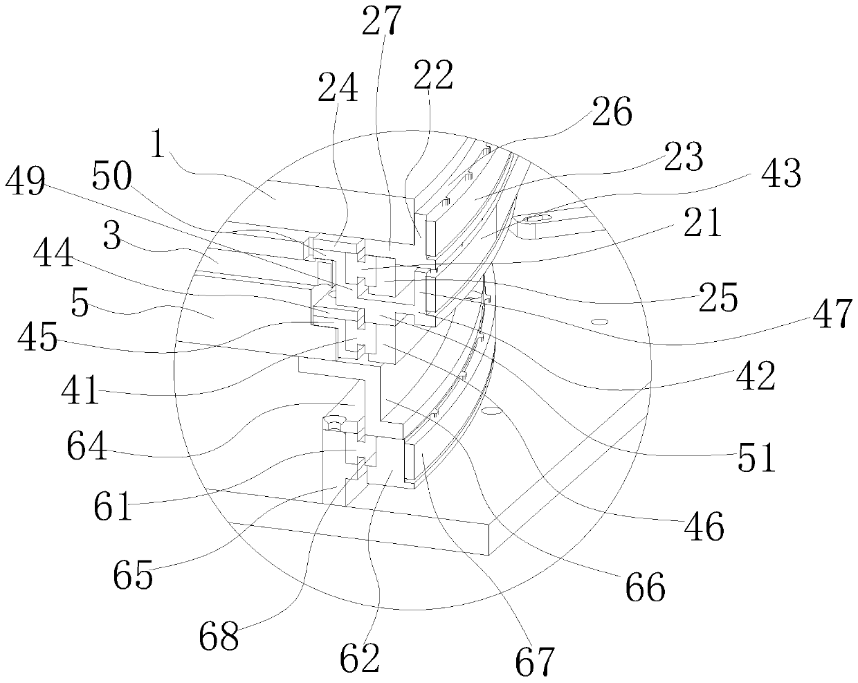
[0050] This embodiment discloses a nested installation structure for satellite antennas in motion, such as Figure 4~6 As shown, it includes the first installation structure, the second installation structure, the third installation structure and the bottom ring seat 65 arranged in layers in sequence:

[0051] The first installation structure includes a thin-walled bearing one 21 and a synchronous pulley 22, the above-mentioned polarizing disc 1 is installed on the synchronous pulley 1 22, and the above-mentioned synchronous pulley 1 22 rotates under the drive of the synchronous belt 1 23 and the servo motor.

[0052] The second installation structure comprises thin-walled bearing two 41 and synchronous pulley two 42, above-mentioned pitching disc 3 is installed on the synchronous pulley two 42, and above-mentioned synchronous pulley two 42 rotates under the drive of synchronous belt two 43 and servo motor.

[0053] The third installation structure includes a thin-walled beari...


PUM


Abstract

The invention discloses a nested mounting structure of a Satcom-on-the-move (SOTM) satellite antenna. The nested mounting structure comprises a first mounting structure having a thin-walled bearing 1and a synchronous pulley 1, wherein a polarizing plate is mounted on the synchronous pulley 1; a second mounting structure having a thin-walled bearing 2 and a synchronous pulley 2, wherein a pitchingplate is mounted on the synchronous pulley 2; and a third mounting structure having a thin-walled bearing 3 and a synchronous pulley 3, wherein an azimuth plate is mounted on the synchronous pulley 3. The synchronous pulley 1 is fixed to the outer ring of the thin-walled bearing 1. The synchronous pulley 2 is fixed to the inner ring of the thin-walled bearing 1 and the outer ring of the thin-walled bearing 2. The synchronous pulley 3 is fixed to the inner ring of the thin-walled bearing 2, and the outer ring of the thin-walled bearing 3. The inner ring of the thin-walled bearing 3 is fixed toa bottom ring seat. The overall profile height of the SOTM satellite antenna mounted by the nested mounting structure can be reduced to below 10CM which is below one-third of that in the prior art, thereby utilizing the space to the utmost extent.

Description

technical field [0001] The invention relates to the technical field of mobile satellite antennas, in particular to a nested installation structure of mobile satellite antennas. Background technique [0002] The mobile communication satellite antenna communication system is a modern satellite communication system capable of uninterrupted real-time communication in motion. The antenna system can always be aligned with the satellite during the movement of various carriers such as vehicles, ships, and airplanes, ensuring continuous satellite communication, thereby realizing uninterrupted voice, data, image and other business transmission capabilities during motion. Traditional mobile communication antennas are mostly parabolic antennas and flat panel array antennas, which are mature in technology and stable in performance. When the disadvantages are large size, heavy weight, complex transmission structure, especially the relatively high profile, the general height is above 30cm...

Claims


Application Information

Patent Timeline
IPC IPC(8): H01Q1/12H01Q1/28H01Q1/32H01Q1/34
CPCH01Q1/12H01Q1/28H01Q1/282H01Q1/285H01Q1/32H01Q1/34
Inventor 王红伟颜荣勤尤清春李东晓杨侃潘强
Owner 苏州灵致科技有限公司
Why Eureka
Try Eureka