
Delayed electric leakage protection circuit

A leakage protection and delay circuit technology, which is applied in emergency protection circuit devices, circuit devices, emergency protection devices with automatic disconnection, etc., can solve problems such as capacitance value changes, leakage malfunctions, and large fluctuations in delay time

Pending Publication Date: 2019-07-02
DELIXI ELECTRIC
View PDF1 Cites 0 Cited by
  • Summary
  • Abstract
  • Description
  • Claims
  • Application Information

AI Technical Summary

Problems solved by technology

However, in some special occasions, when there is leakage, the customer only needs to disconnect a certain branch, and does not want to affect the normal operation of other equipment. At this time, the leakage protector installed on the upper level is required to have a certain delay. Time function, and this delay time must be greater than the disconnection time of the leakage protector of the next level, and in the existing delay type miniature circuit breakers, most of them are realized by capacitor delay time
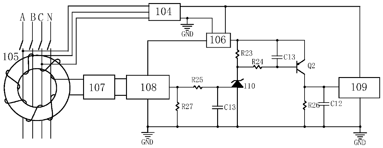
[0003] For example, a time-delay leakage protection circuit is disclosed in the Chinese patent application number 201520439129.2, as attached figure 1 As shown, it adopts the method of RC parallel connection, allowing the capacitor to charge and discharge to realize the control of the delay time. Although this method is simple and can also achieve the purpose of delay, the capacitor may cause temperature drift with the change of the ambient temperature. As a result, the capacitance value changes, causing the delay time to be unstable. Moreover, there is a certain error in the capacitance value of ordinary capacitors on the market. Due to the capacitance, the delay time fluctuates in a large range, about ±20%. There may be a risk of leakage and misoperation of the product during use

Method used


Image

  • Delayed electric leakage protection circuit
  • Delayed electric leakage protection circuit
  • Delayed electric leakage protection circuit

Examples


Embodiment Construction

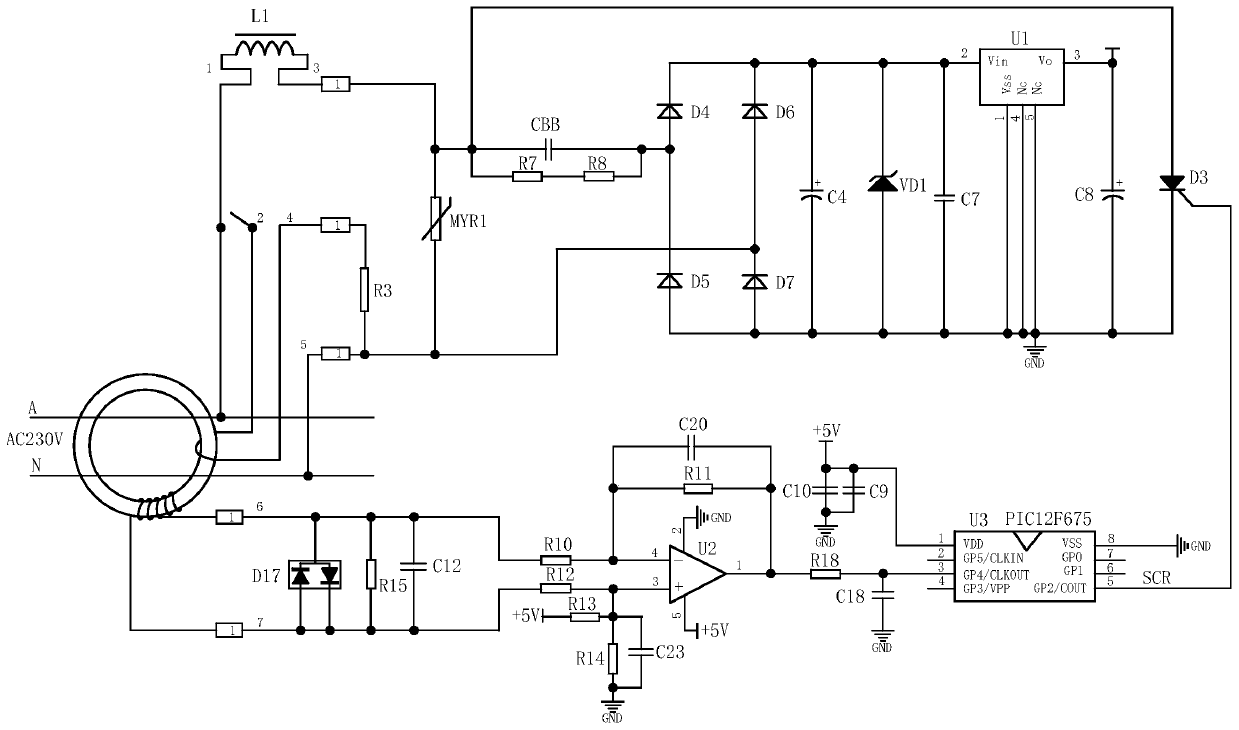
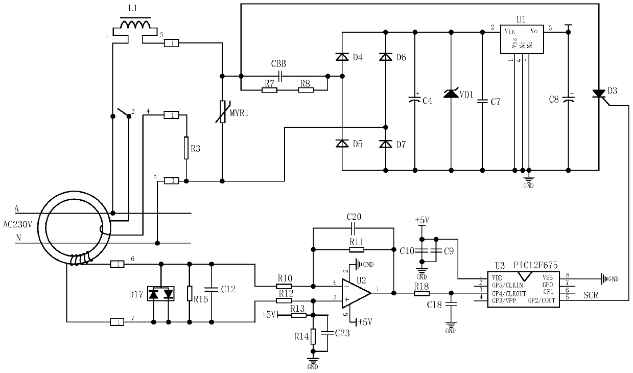
[0021] The specific embodiment of the present invention is such as Figure 1-2 As shown, a delay type leakage protection circuit includes a transformer, a power circuit module, a leakage signal detection module and a tripping circuit module, and also includes a delay circuit module, and the delay circuit module includes a single-chip microcomputer U3, a capacitor C9 and Capacitor C10, capacitor C9 and capacitor C10 are connected in parallel to pin 1 of the single-chip microcomputer U3. The power supply of the single-chip microcomputer U3 is +5V, and the power supply is provided by the power circuit module.

[0022] The above-mentioned power supply circuit module includes a piezoresistor MYR1, a resistance-capacitance step-down circuit, a rectification filter circuit and a power supply voltage stabilization circuit.

[0023] The above-mentioned RC step-down circuit includes a CBB capacitor, a resistor R7 and a resistor R8, and the resistor R7 and the resistor R8 are connected i...


PUM


Abstract

The invention relates to the technical field of electric leakage protection circuits and in particular to a delayed electric leakage protection circuit, which comprises a transformer, a power circuitmodule, an electric leakage signal detection module, a trip circuit module and a delay circuit module, wherein the delay circuit module includes a single-chip microcomputer U3, a capacitor C9 and a capacitor C10; the capacitor C9 and the capacitor C10 are connected in parallel and then are connected to the pin 1 of the single-chip microcomputer U3; the single-chip microcomputer U3 is powered by +5V power provided by the power circuit module. The delayed electric leakage protection circuit amplifies an electric leakage signal by a differential operational amplifier, then processes the electricleakage signal and controls the electric leakage delay time through the single-chip microcomputer, and realizes precise electric leakage delay operation and time control.

Description

technical field [0001] The invention relates to the technical field of leakage protection circuits, in particular to a time-delay type leakage protection circuit. Background technique [0002] At present, most of the micro-leakage protectors on the market are non-delay type, because under normal circumstances, micro-leakage protectors are used to protect personal safety. When a leakage occurs, it is hoped that the circuit breaker will be disconnected as soon as possible. , so generally there is no delay. However, in some special occasions, when there is leakage, the customer only needs to disconnect a certain branch, and does not want to affect the normal operation of other equipment. At this time, the leakage protector installed on the upper level is required to have a certain delay. Time function, and this delay time must be greater than the disconnection time of the leakage protector of the next level, and in the existing time-delay miniature circuit breakers, most of th...

Claims


Application Information

Patent Timeline
IPC IPC(8): H02H3/34
CPCH02H3/34
Inventor 潘秀菊丁小伟
Owner DELIXI ELECTRIC
Learn More