Heart mitra clip

A mitral valve and heart technology, applied in medical science, surgery, etc., can solve the problems of large surgical injuries, many related complications, and the inability of elderly patients to receive treatment, so as to achieve accurate motion control and avoid blood reflux

Pending Publication Date: 2019-07-05
MALLOW MEDICAL SHANGHAICO LTD
View PDF0 Cites 3 Cited by
  • Summary
  • Abstract
  • Description
  • Claims
  • Application Information

AI Technical Summary

Problems solved by technology

The traditional treatment for mitral valve regurgitation is valve repair or valve replacement. However, due to the large s

Method used


Image

  • Heart mitra clip
  • Heart mitra clip
  • Heart mitra clip

Examples


Example Embodiment

[0079] Example 1

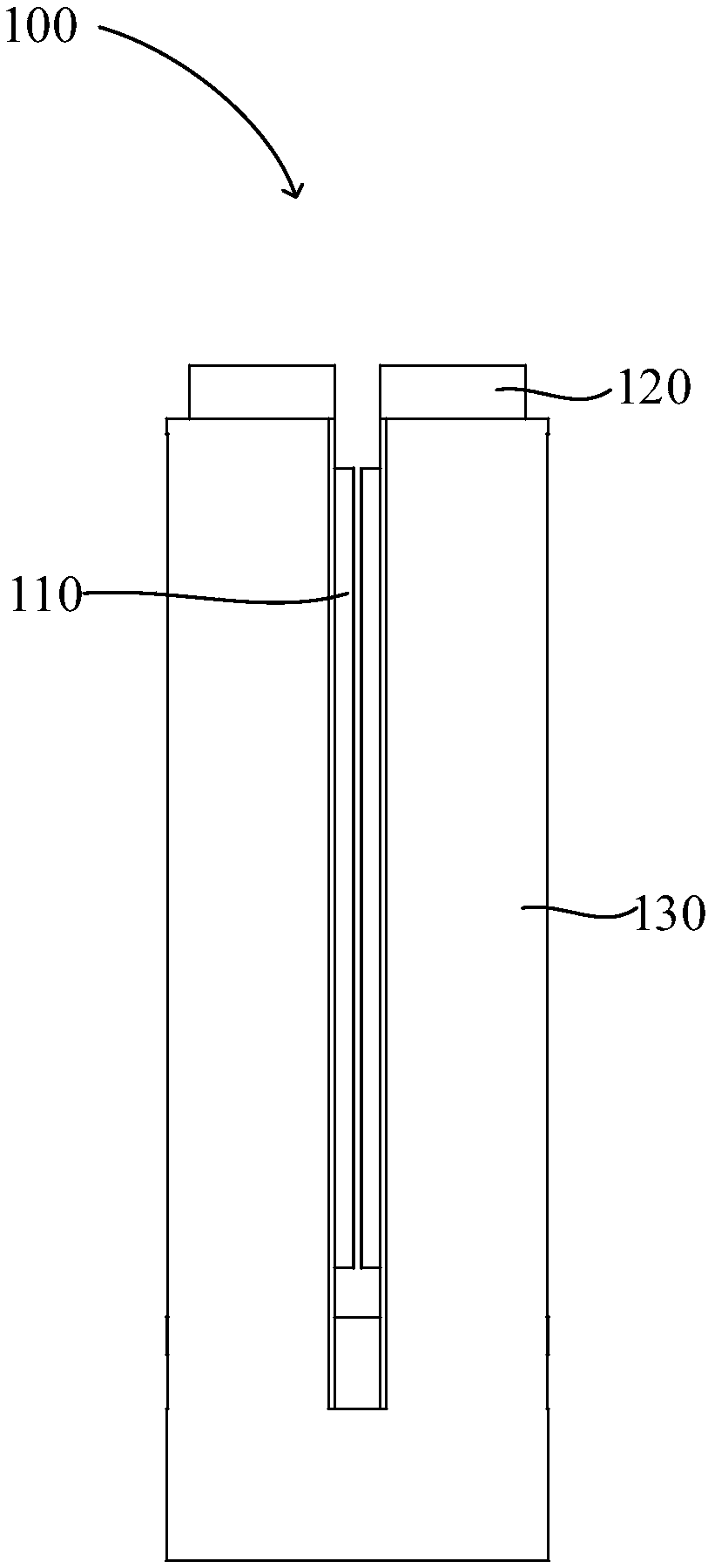
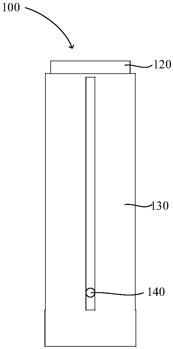
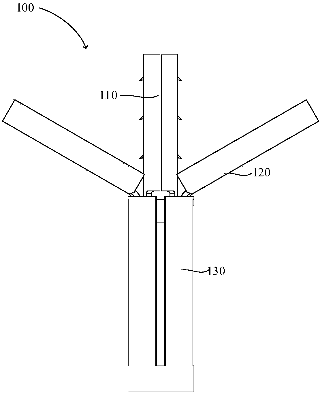
[0080] like Figure 1-5 As shown, a cardiac mitral valve clip 100 includes: a first valve clip 110 , a second valve clip 120 , a third valve clip 130 and a limiting mechanism 140 . The limiting mechanism 140 is used to limit the first valve clamp 110 to slide away from the second valve clamp 120 or to limit the second valve clamp 120 to slide away from the third valve clamp 130 . In this embodiment, the limiting structure is used to limit the second flap clip 120 from sliding away from the third flap clip 130 , so as to prevent the second flap clip 120 from being separated from the third flap clip 130 . Since the first valve clamp 110 and the second valve clamp 120 will form a clamping state (will be described in detail below), the limiting structure is used to limit the second valve clamp 120 from sliding away from the third valve clamp 130, that is to say, the limiting structure is used The combination of the first clip 110 and the second clip 120 is lim...

Example Embodiment

[0098] Example 2

[0099] like Figure 18-21 As shown, the cardiac mitral valve clip 100 of the second embodiment is basically the same as that of the first embodiment. The difference is that in this embodiment, the limiting mechanism 140 includes an inner limiting mechanism 141 and an outer limiting mechanism. The inner limiting mechanism 141 is used to limit the first flap clip 110 from sliding away from the second flap clip 120 , so as to prevent the first flap clip 110 from being separated from the second flap clip 120 . The outer limiting mechanism is used to limit the second flap clip 120 from sliding away from the third flap clip 130 , so as to prevent the second flap clip 120 from being separated from the third flap clip 130 . Since the first valve clamp 110 and the second valve clamp 120 will form a clamping state, the outer limit structure is used to limit the second valve clamp 120 to slide away from the third valve clamp 130, that is to say, the outer limit struc...

Example Embodiment

[0102] Example 3

[0103] like Figure 22-23 As shown, the cardiac mitral valve clip 100 of the third embodiment is basically the same as that of the first embodiment. The difference is that in this embodiment, the first flap clip 110 , the second flap clip 120 , and the third flap clip 130 are all provided with rounded corners to avoid abrupt right angles, thereby avoiding damage to internal tissues. It should be noted that the drawings show only schematic structures, and the present invention does not limit the size of the rounded corners.


PUM


Abstract

The invention discloses a heart mitra clip. The heart mitra clip comprises a first mitra clip, a second mitra clip, a third mitra clip and a limiting mechanism, wherein the first mitra clip is provided with a first left mitra clip and a first right mitra clip which are symmetrical; the second mitra clip is provided with a second left mitra clip and a second right mitra clip which are symmetrical,and can be arranged on the first mitra clip in a sliding and sleeving manner; the third mitra clip can be arranged on the second mitra clip in a sliding and sleeving manner; and the limit mechanism isused for limiting the first mitra clip from leaving away from the second mitra clip in a sliding manner or limiting the combination of the first mitra clip and the second mitra clip from leaving awayfrom the third mitra clip in a sliding manner. The heart mitra clip can enter the heart through a duct, for the mitra which cannot be normally opened and closed, the first left mitra clip and the second left mitra clip can clamp the left valve leaflet, the first right mitra clip and the second right mitra clip can clamp the right valve leaflet, the combination of the first mitra clip and the second mitra clip is dragged into the third mitra clip, and blood regurgitation is avoided; and the limit mechanism enables movement control to be more accurate, and the situation that the first mitra clip is separated from the second mitra clip, or the combination of the first mitra clip and the second mitra clip is separated from the third mitra clip is avoided.

Description

technical field [0001] The invention relates to a heart mitral valve clip. Background technique [0002] With the advent of population aging, the incidence of heart valve disease has increased significantly. The traditional treatment for mitral valve regurgitation is valve repair or valve replacement. However, due to the large surgical injury and many related complications, many elderly patients with severe valvular disease cannot receive treatment. In recent years, surgical treatment of valvular heart disease has gradually become minimally invasive. Interventional treatment of valvular heart disease has developed rapidly due to its advantages of less trauma, relative safety, and good curative effect. The curative effect of treatment is more certain, and some new technologies have become new hotspots in interventional cardiology research. Contents of the invention [0003] The technical problem to be solved by the present invention is to provide a heart mitral valve clip...

Claims


Application Information

Patent Timeline
IPC IPC(8): A61B17/00
CPCA61B17/0057A61B2017/00575A61B2017/00584A61B2017/00646
Inventor 张瑾张健马彩霞程海波
Owner MALLOW MEDICAL SHANGHAICO LTD
Why Eureka
Try Eureka