Vacuum belt dryer

A technology of vacuum belt drying and conveyor belt, which is applied in the direction of evaporator accessories, spray evaporation, etc., which can solve the problems of waste, small spraying height, and unsmooth discharge, achieve good solubility and preservation, improve drying efficiency, and reduce The effect of human cost

Pending Publication Date: 2019-07-05
内蒙古恒光大药业股份有限公司
View PDF1 Cites 1 Cited by
  • Summary
  • Abstract
  • Description
  • Claims
  • Application Information

AI Technical Summary

Problems solved by technology

[0004] The disadvantages of the above patented technology are: 1) The raw material is sprayed on the uppermost conveyor belt, the spraying height is small, the spray drying effect is not significant, and the slurry raw material is easy to spray to both sides of the conveyor belt and fall to the bottom of the cylinder, resulting in waste and needs to be cleaned regularly ;2) During the process of the dried raw materials falling from the upper layer to the lower layer, some of them have agglomerated and are easy to fall on the outside of the conveyor belt. In addition, the distribution of raw materials falling on the lower conveyor belt is uneven, which affects the drying effect; 3) Dried The material is agglomerated, and there are problems such as unsmooth discharge; 4) The diameter of the cylinder cover can reach about 3 meters. During maintenance or inspection, a large and heavy cylinder cover needs to be designed with a cylinder cover lifting frame

Method used


Image

  • Vacuum belt dryer
  • Vacuum belt dryer
  • Vacuum belt dryer

Examples


Embodiment Construction

[0039] The present invention will be described in detail below in conjunction with the accompanying drawings.

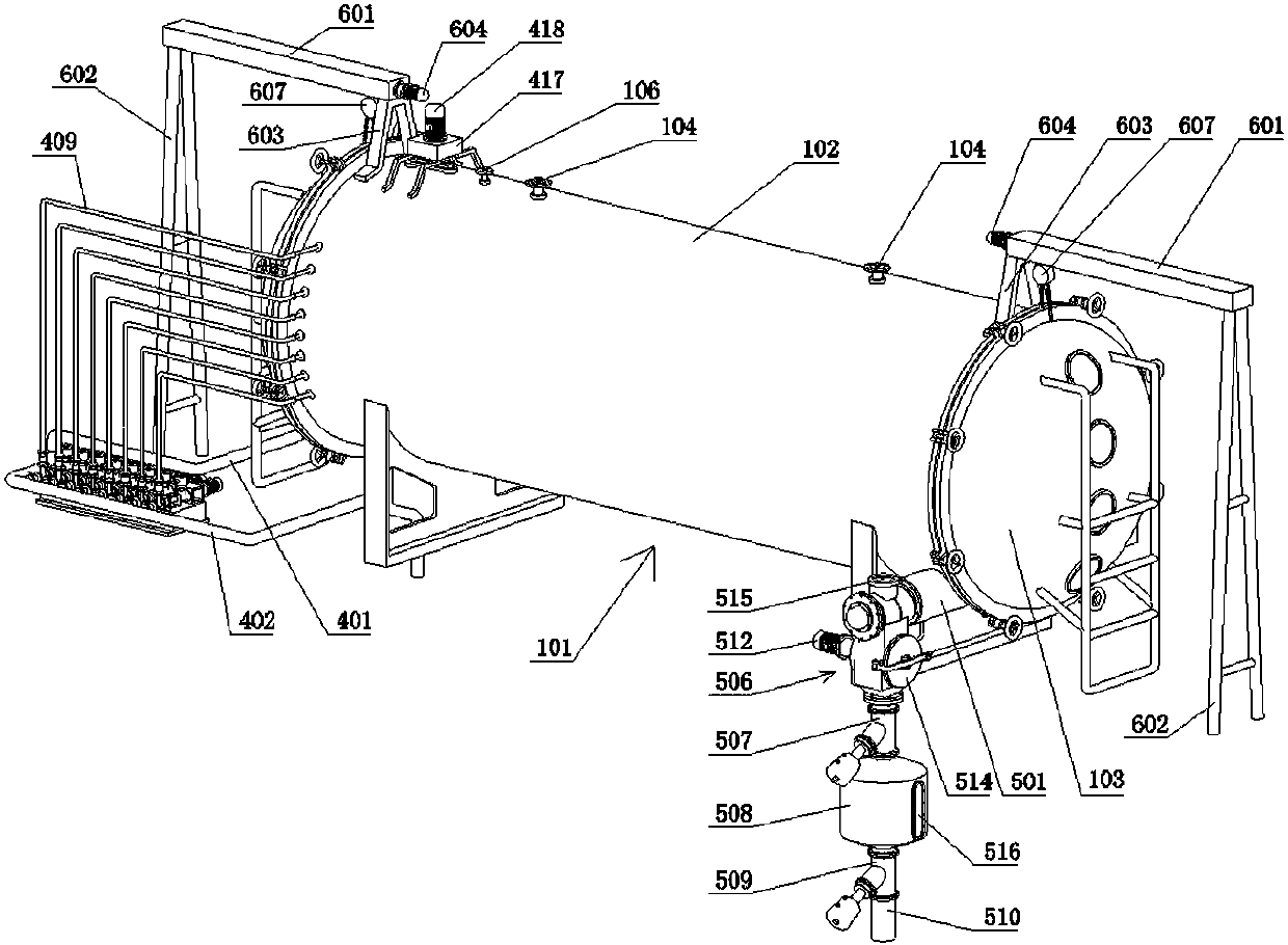
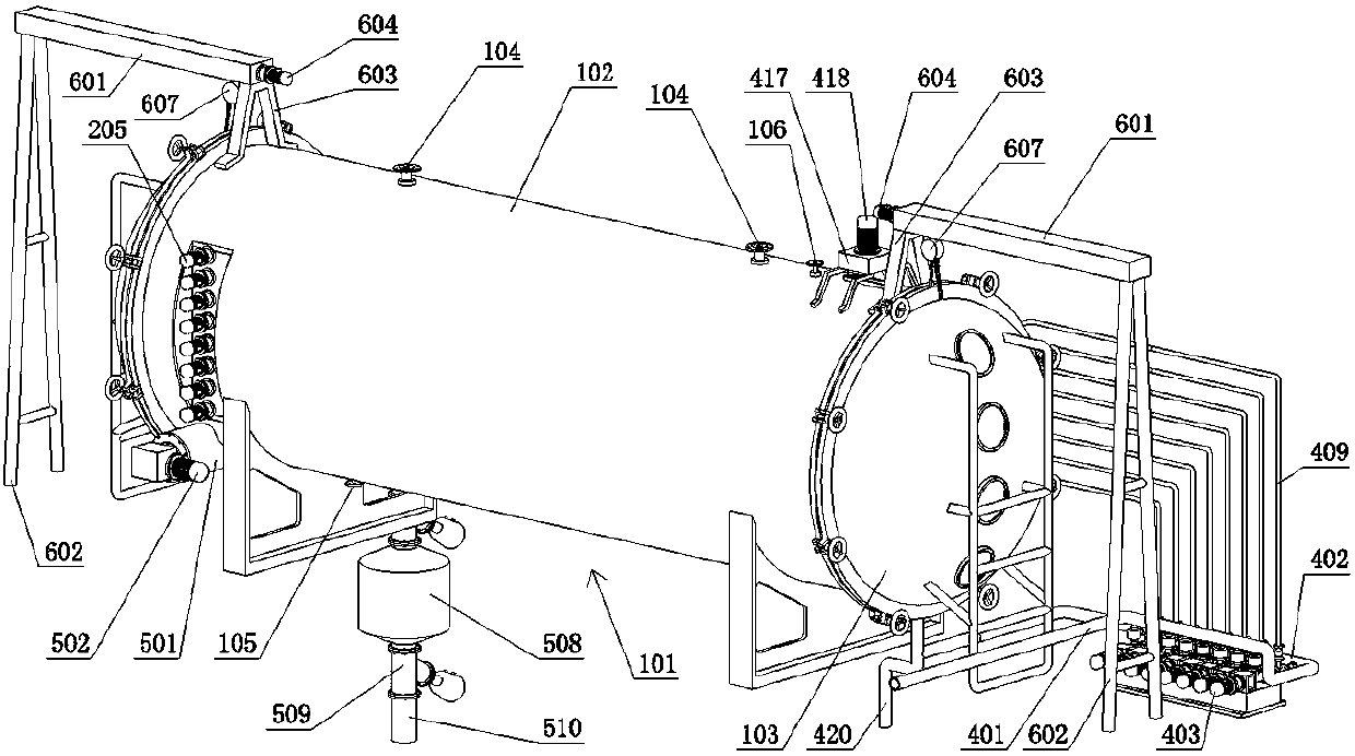
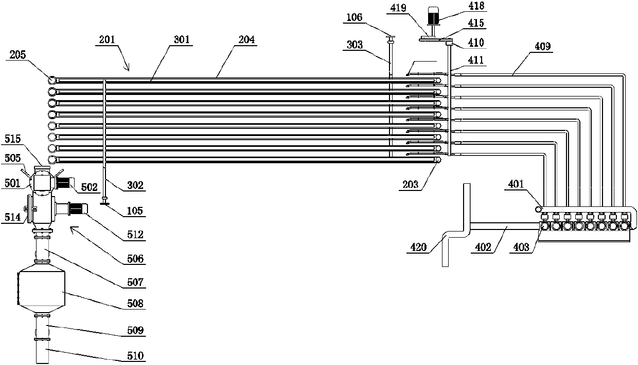
[0040] Such as Figure 1 to Figure 4 As shown, a vacuum belt dryer includes a cylinder 101 composed of a cylinder 102 and cylinder covers 103 at both ends, an 8-layer conveyor belt 201 arranged inside the cylinder 101, a feeding system and a discharging system; the cylinder 102 There is a vacuum port 104, a heat source inlet 105 and a heat source outlet 106; the conveyor belt 201 is composed of a driving roller 202, a driven roller 203 and a belt 204; a lifting upper belt 204 is provided between the driving roller 202 and the driven roller 203 One end of the heating plate 301 is connected to the heat source inlet 105 through the heating pipe 302, and the other end of the heating plate 302 is connected to the heat source outlet 106 through the heat return pipe 303; The co-rotating conveying motor 205 is driven to rotate to synchronously convey the material from the f...


PUM


Abstract

A vacuum belt dryer is disclosed which includes a cylinder body, multiple conveyor belt layers arranged inside the cylinder body, a feeding system and a discharging system. Conveying motors of conveyor belts convey a slurry raw material from feeding ends to discharging ends synchronously. The feeding system achieves material supplying through screw pumps and feeding branch pipelines, with the number of the screw pumps being same as the number of the conveyor belt layers. Swing arms on a vertical shaft and extending to feeding ends of the conveyor belt layers are driven to swing back and forthby a material paving motor through a crank. Material nozzles on the swing arms and communicating with the feeding branch pipelines uniformly arrange the slurry raw material onto the conveyor belts. The discharging system includes a discharging pipe in which a screw rod is arranged. A crusher, a first discharging valve, a middle storage tank, a second discharging valve and a powder outlet are arranged in order below the discharging end of the discharging pipe. The vacuum belt dryer can achieve automatic continuous drying, a high drying efficiency, uniform distribution of the slurry raw material, smooth discharging of a finished dried product, convenient maintenance, and good product quality after drying.

Description

technical field [0001] The invention belongs to the technical field of drying equipment, in particular to a vacuum belt dryer. Background technique [0002] The traditional Chinese medicine extraction process includes extraction, concentration and drying steps. The concentrated Chinese medicine extract is a viscous paste, which is not resistant to high temperature, some are highly viscous and easy to agglomerate, and some are thermoplastic or heat-sensitive materials; therefore, it is not suitable for It is difficult or impossible to use traditional dryers (such as spray dryers, ovens, etc.) for drying. However, the use of freeze-drying technology (such as low-temperature drying machines) not only takes a long time to dry, but also has low drying efficiency and high energy consumption, and the drying degree of the product is uneven, which affects product quality. At the same time, some dryers cannot achieve the purpose of continuous drying. [0003] Therefore, the vacuum b...

Claims


Application Information

Patent Timeline
Patent Type & Authority Applications(China)
IPC IPC(8): B01D1/18B01D1/30
CPCB01D1/18B01D1/30
Inventor 战文李海华肖发君陈志强
Owner 内蒙古恒光大药业股份有限公司
Why Eureka
Try Eureka