
Pulse power generation circuit and electrical dust catcher

A technology for generating circuits and pulse power supplies, applied in power supply technology, electrostatic separation, etc., can solve the problems of limited scope of application, single pulse source, etc., and achieve the effect of less consumption

Pending Publication Date: 2019-07-05
SICHUAN ENERGY INTERNET RES INST TSINGHUA UNIV +1
View PDF0 Cites 1 Cited by
  • Summary
  • Abstract
  • Description
  • Claims
  • Application Information

AI Technical Summary

Problems solved by technology

[0005] The object of the present invention is to provide a pulse power generation circuit and an electrostatic precipitator to solve the problems in the prior art that the pulse source generated by the pulse power generation circuit is single and the scope of application is relatively limited.

Method used


Image

  • Pulse power generation circuit and electrical dust catcher
  • Pulse power generation circuit and electrical dust catcher
  • Pulse power generation circuit and electrical dust catcher

Examples


no. 1 example

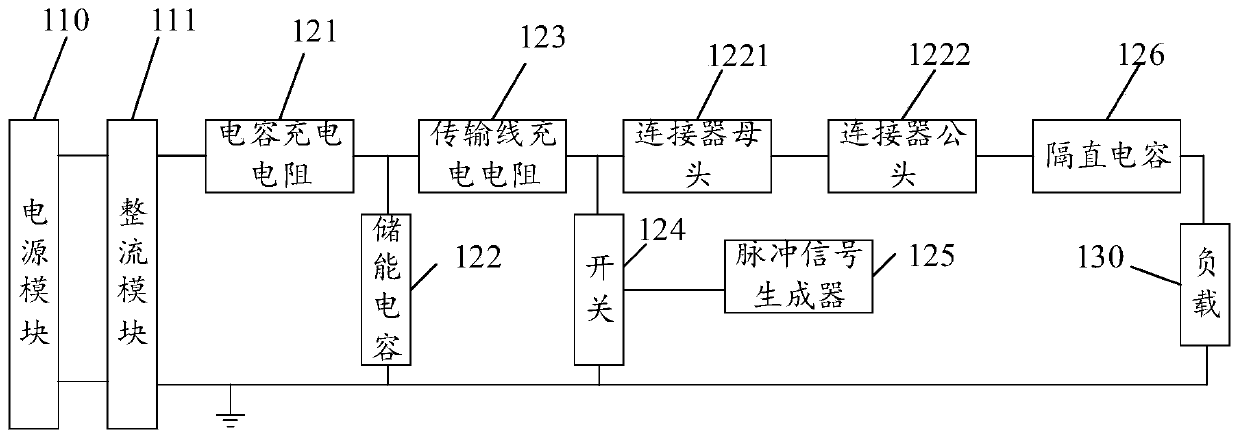
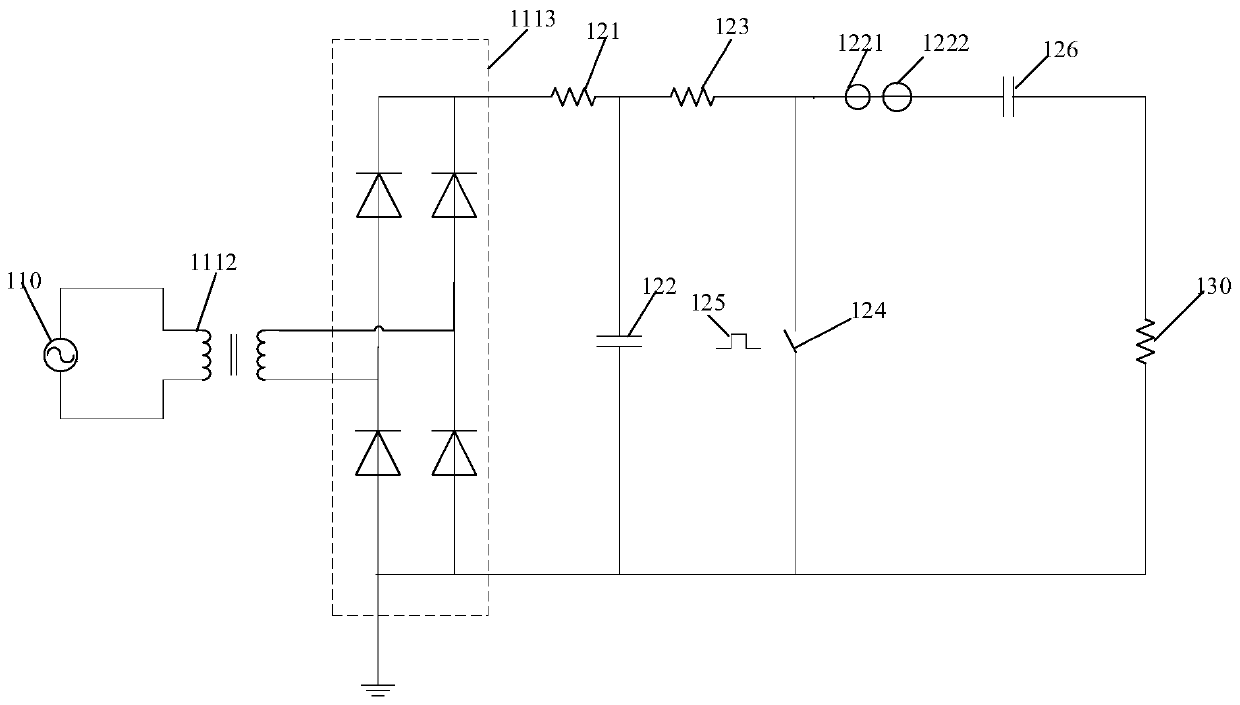
[0038] Please refer to figure 1 , figure 2 and image 3 , figure 1 A schematic diagram of a pulse power generation circuit device provided in the embodiment of the present application; figure 2 The schematic diagram of the pulse power generation circuit provided by the embodiment of the present application, image 3 A schematic diagram of a pulse power generating circuit provided in an embodiment of the present application. The embodiment of the present application provides a pulse power generating circuit, including: a power module 110, a pulse generating module 120 and a load 130; wherein, the pulse generating module 120 is connected in series with the power module 110, and the load 130 is connected in parallel at both ends of the pulse generating module 120 .

[0039] It should be noted that the power module 110 is used to provide voltage for the circuit. Optionally, the power module 110 may use a single-phase AC power supply or a three-phase AC power supply. The pu...

no. 2 example

[0068] The embodiment of the present application also provides an electrostatic precipitator, including an electrostatic precipitator body and the pulse power generation circuit in the first embodiment. Among them, the pulse power generation circuit is applied in the electrostatic precipitator body.

[0069] Optionally, the above-mentioned pulse power generation circuit can also be applied to laser technology, accelerator technology or instant photography technology, which can meet various technical occasions that require a mixed-frequency pulse source.


PUM

PropertyMeasurementUnit
Resistanceaaaaaaaaaa

Abstract

The invention provides a pulse power supply generation circuit and an electrical dust catcher, and relates to the technical field of pulse power supplies. The circuit comprises a power supply module,a pulse generation module and a load, the pulse generation module and the power supply module are connected in series, the load is connected in parallel with two ends of the pulse generation module, the pulse generation module comprises a capacitance charging resistor, an energy storage capacitor, a transmission line charging resistor, a switch, a pulse signal generator and a high-voltage connector, the capacitance charging resistor, the transmission line charging resistor and the high-voltage connector are connected in series, one end of the energy storage capacitor is connected between the capacitance charging resistor and the transmission line charging resistor, the other end of the energy storage capacitor is connected with ground, one end of the switch is connected between the transmission line charging resistor and the high-voltage connector, the other end of the switch is connected with the ground, and the pulse signal generator is electrically connected with the switch. By thepulse power supply generation circuit, frequency-adjustable pulse strings can be generated, meanwhile, a single pulse frequency in each pulse string is also adjustable, so that the circuit is suitablefor various application occasions.

Description

technical field [0001] The invention relates to the technical field of pulse power supply, in particular to a pulse power supply generating circuit and an electric dust collector. Background technique [0002] Pulse power technology is a new science and technology developed from the needs of national defense, and it is one of the research hotspots of major countries in the world today. High-voltage pulse power supplies are widely used in the fields of accelerator technology, laser technology, electrostatic precipitator technology and instant photography technology. [0003] In the existing transmission line pulse technology, the pulse generation circuit usually uses a power electronic switch, and the transmission line used is matched with the load, that is, the load resistance is equal to the wave impedance of the transmission line, and the conduction of the power electronic switch is controlled by the button switch and the power supply, thereby generate a pulse. [0004] ...

Claims


Application Information

Patent Timeline
IPC IPC(8): B03C3/66
CPCB03C3/66
Inventor 朱鑫磊邹晓兵王新新罗海云孙汝岳黄昆
Owner SICHUAN ENERGY INTERNET RES INST TSINGHUA UNIV
Learn More