Continuous material belt type metal part efficient electroplating and cutting integrated flow line

A technology of assembly line and metal parts, which is applied in the field of high-efficiency electroplating and cutting integrated assembly line for continuous strip-type metal parts, which can solve the problems such as the inability to meet the cleanliness requirements of medical products, the inability to meet the assembly and use of finished products, and the difficulty in reducing the cutting processing time. , to achieve the effect of reducing handling and transportation links, saving space utilization costs, and improving processing efficiency

Pending Publication Date: 2019-07-05
LEOCO SUZHOU PRECISE IND
View PDF0 Cites 2 Cited by
  • Summary
  • Abstract
  • Description
  • Claims
  • Application Information

AI Technical Summary

Problems solved by technology

[0006] 1. The two processes of coil receiving after electroplating and coil unloading before punching make it difficult to reduce the overall electroplating and cutting processing time of metal parts, with high time cost and low efficiency; 2. Due to many processes, it is necessary to Repeated handling and transportation of packaged materials in rolls increases the cost; 3. Repeated handling and transportation processes are also prone to product deformation and other quality abnormalities, which cannot meet the requirements for subsequent assembly and use of finished products; 4. Electroplating and cutting needs Different production workshops are occupied respectively, and the space utilization rate is low; 5. Due to many processes, there is a possibility of product contamination during handling and transportation, which cannot meet the cleanliness requirements of medical products

Method used


Image

  • Continuous material belt type metal part efficient electroplating and cutting integrated flow line
  • Continuous material belt type metal part efficient electroplating and cutting integrated flow line
  • Continuous material belt type metal part efficient electroplating and cutting integrated flow line

Examples


Embodiment Construction

[0039] The present invention will be further described below in conjunction with the drawings and embodiments:

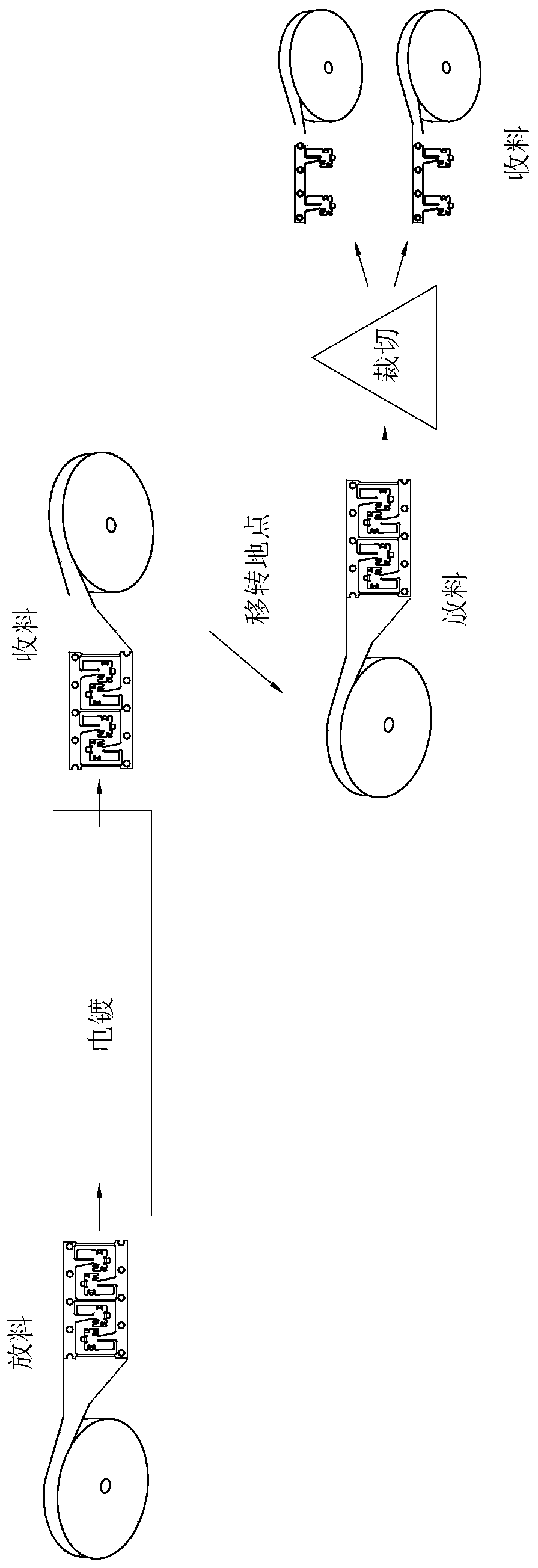
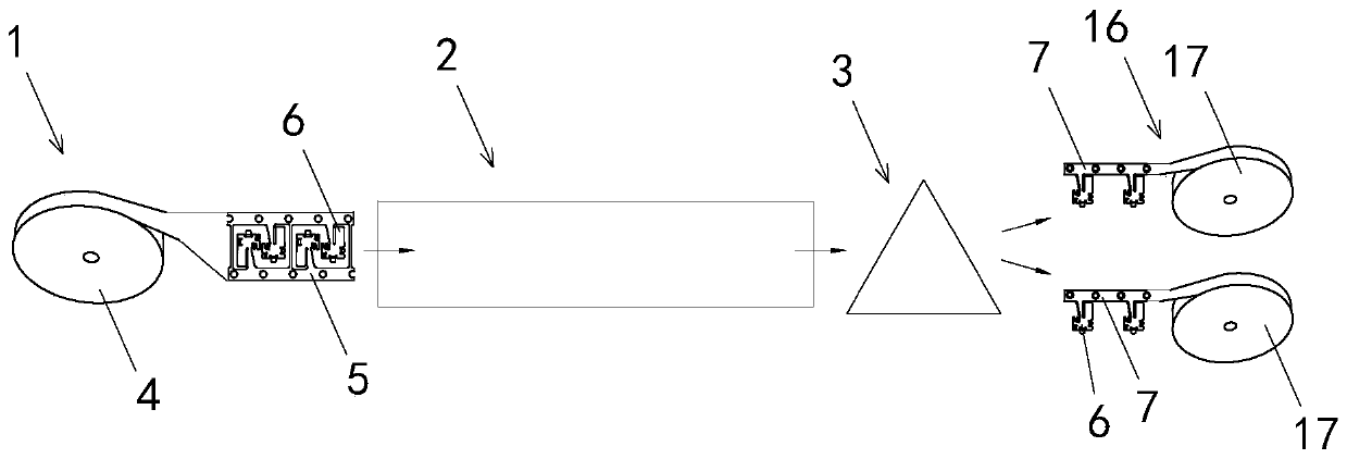
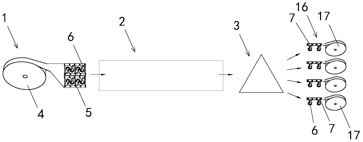
[0040] Example: see attached Figure 2~7 As shown, a continuous strip-type metal piece high-efficiency electroplating and cutting integrated assembly line; according to the processing order, it includes a discharge unit 1, an electroplating unit 2, and a cutting unit 3 from front to back along the X axis.

[0041] The unwinding unit 1 includes a rotation positioning mechanism (not shown in the figure) for a first material roll 4, which is a continuous material strip type material metal product to be electroplated after being packaged in a package, The positioning mechanism may be a rotating shaft, the length of the rotating shaft corresponds to the Y-axis direction, and is rotatably connected to a frame (not shown in the figure) of the assembly line; the first roll 4 is sleeved on the rotating shaft with its rotation center On; the first roll 4 is horizontally discharge...


PUM


Abstract

The invention discloses a continuous material belt type metal part efficient electroplating and cutting integrated flow line. The continuous material belt type metal part efficient electroplating andcutting integrated flow line comprises a discharging unit, an electroplating unit and a cutting unit. The discharging unit comprises a first material roll which performs horizontal discharging in a material belt mode through rotation, and a material belt enters the electroplating unit for electroplating; the electroplating unit delivers the material belt into the cutting unit for cutting after finishing electroplating of the material belt, and thus electroplated metal parts are cut out from the material belt, or the electroplated material belt is divided into at least two branch material belts; the flow line further comprises a material belt conveying control unit which corresponds to the electroplating unit and the cutting unit; and the control unit comprises at least one pulling mechanism, and the material belt is driven by the pulling mechanisms to perform displacement from the electroplating unit into the cutting unit. The electroplating unit is connected with the cutting unit in series through the material belt conveying control unit, the conveying speed of the portions, in the electroplating unit and the cutting unit, of the material belt is balanced, and thus stable and reliable production of the flow line can be guaranteed after integration.

Description

Technical field [0001] The present invention relates to the technical field of electroplating metal parts processing, in particular to a continuous strip-type metal part high-efficiency electroplating and cutting integrated assembly line, which includes the electroplating of continuous strip-type metal parts and removing the metal parts from the strip after the electroplating is completed. Cutting. The metal parts include but are not limited to metal terminals, metal contact pieces, and other metal parts. Background technique [0002] Metal parts, especially metal parts plated on the surface, are widely used in electronic products. Some of them are directly used in finished products, and some are assembled into parts and used by plastic parts. Because there are welding requirements, or requirements to prevent environmental corrosion, or to match the requirements of plug wear, often a layer of tin or gold or silver is electroplated on metal parts. [0003] Although most of the me...

Claims


Application Information

Patent Timeline
Patent Type & Authority Applications(China)
IPC IPC(8): B23P23/04
CPCB23P23/04
Inventor 邱宏华
Owner LEOCO SUZHOU PRECISE IND
Why Eureka
Try Eureka