
Ultra-thin external rotor harmonic deceleration integrated machine

A technology of harmonic deceleration and external rotor, applied in the direction of manipulators, program-controlled manipulators, manufacturing tools, etc., can solve the problems of unsatisfactory requirements and long length, and achieve the effects of compact structure, stable output and simple installation.

Pending Publication Date: 2019-07-05
江苏开璇智能科技有限公司
View PDF0 Cites 5 Cited by
  • Summary
  • Abstract
  • Description
  • Claims
  • Application Information

AI Technical Summary

Problems solved by technology

[0003] 1. The standard servo motor and harmonic reducer are combined into a harmonic reducer integrated machine. The structure combined with the harmonic reducer through connecting flanges and other connecting mechanisms is often very long and can only be used in industries. Robots and other fields that are not sensitive to the length of the harmonic reducer
[0004] 2. Combination of frameless motor module and harmonic reducer, this structure can be shortened by one grade in length compared with the first scheme, but for some service robot industries with strict length requirements, the above two schemes still cannot meet Require

Method used


Image

  • Ultra-thin external rotor harmonic deceleration integrated machine
  • Ultra-thin external rotor harmonic deceleration integrated machine
  • Ultra-thin external rotor harmonic deceleration integrated machine

Examples


Embodiment Construction

[0045] The present invention will be further described in detail below in conjunction with the accompanying drawings, so that those skilled in the art can implement it with reference to the description.

[0046] It should be understood that terms such as "having", "comprising" and "including" as used herein do not entail the presence or addition of one or more other elements or combinations thereof.

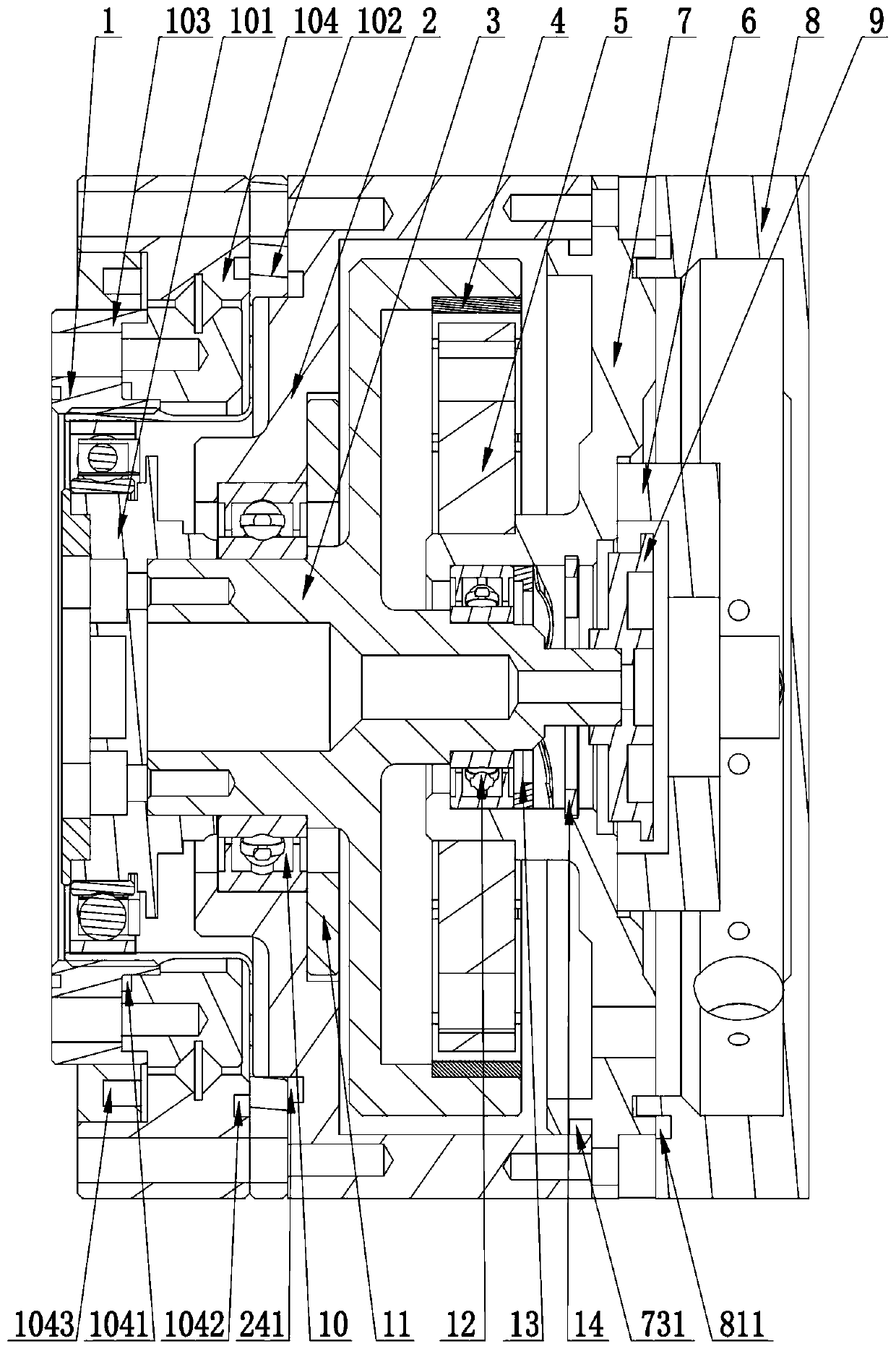
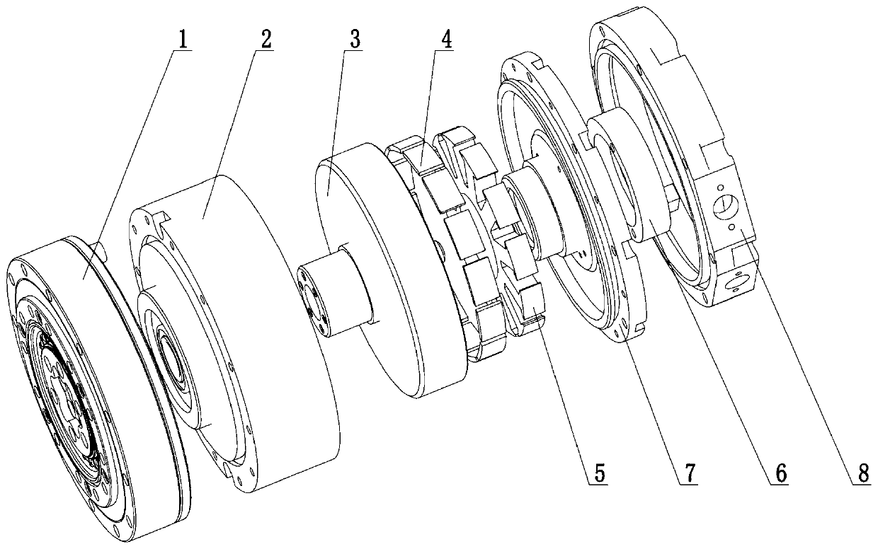
[0047] see figure 1 and figure 2, the present invention provides a technical solution: an ultra-thin external rotor harmonic speed reducer, including a motor and a harmonic speed reducer 1 .

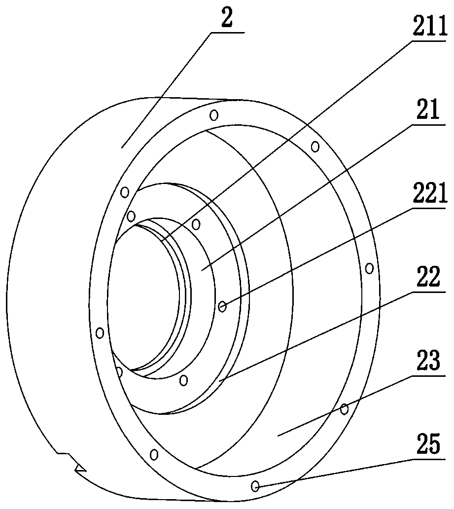
[0048] Specifically, the motor includes: a casing 2 , a rotor 3 and a stator 5 . In this embodiment, the casing 2 is a multi-stage hollow barrel structure, the outer periphery of the rear end cover 7 is sealed and fixed on the tail opening of the casing 2, and the center of the axis of the rear end cover 7 extends toward the inside of the casing 2 to set a hollow stator shaft. 71. The r...


PUM


Abstract

The invention discloses an ultra-thin external rotor harmonic deceleration integrated machine comprising a motor and a harmonic reducer. The motor comprises a machine shell, a rear end cover, a rotorand a stator; the machine shell is of a multi-stage hollow barrel-shaped structure, the outer circumference of the rear end cover is fixed to a tail opening of the machine shell in a sealed manner, the shaft center of the rear end cover extends towards the interior of the machine shell to be provided with a hollow stator shaft, the rotor comprises a rotor shaft rotationally arranged in the machineshell and magnetic steel arranged on the outer circumference of the rotor shaft, and the stator is mounted on the outer circumference of the hollow stator shaft; and the harmonic reducer comprises awave generator connected to the first end of the rotor shaft in the axial direction, a flexible wheel, a rigid wheel and a crossed roller bearing, the outer circumference of the flexible wheel is fixed to the front end wall of the machine shell, the flexible wheel is arranged on the outer circumference of the wave generator, the rigid wheel is arranged on the outer circumference of the flexible wheel in a sleeving manner, and the crossed roller bearing is located between the rigid wheel and the machine shell in the axial direction. According to the ultra-thin external rotor harmonic deceleration integrated machine, the outer rotor structure is used on the basis of a frameless motor, the external rotor is directly connected with the reducer, and the advantages of being flat in structure, simple in installation, stable in output, high in structural compatibility and the like are achieved.

Description

technical field [0001] The invention relates to the field of drive of a motor, a reducer and a driving system integrating an integrated machine for robot joints, in particular to an ultra-thin external rotor harmonic deceleration integrated machine for driving joints of service robots. Background technique [0002] The harmonic reducer integrated machine is the drive actuator used to drive the robot's connecting rod at the joint of the robot. It is a new type of robot-specific drive actuator that integrates the servo motor, harmonic reducer, and drive system. At present, there are two main forms of the composition structure of the series harmonic reducer: [0003] 1. The standard servo motor and harmonic reducer are combined into a harmonic reducer integrated machine. The structure combined with the harmonic reducer through connecting flanges and other connecting mechanisms is often very long and can only be used in industries. Robots and other fields that are not sensitive...

Claims


Application Information

Patent Timeline
IPC IPC(8): B25J17/00B25J9/10B25J9/12
CPCB25J17/00B25J9/1025B25J9/126
Inventor 李文昊储建华蒯佳君王刚
Owner 江苏开璇智能科技有限公司
Learn More