T-shaped beam casting special mold and using method thereof

A mold and mold-oriented technology, applied in molds, mold fixtures, mold auxiliary parts, etc., can solve the problems of insufficient practicability, low quality of T-beams, and insufficient functions, saving internal space, perfect functions, space saving effect

Pending Publication Date: 2019-07-05
SICHUAN EAST SPRING MACHINERY EQUIP MFG CO LTD
View PDF13 Cites 12 Cited by
  • Summary
  • Abstract
  • Description
  • Claims
  • Application Information

AI Technical Summary

Problems solved by technology

[0011] The purpose of the present invention is: in order to solve the technical problems of existing T-beam casting molds with many defects, imperfect functions, insufficient practicability, and relatively low quality of T-beams obtained by casting, the present invention provides a T-beam casting mold. Special mold and its usage method

Method used


Image

  • T-shaped beam casting special mold and using method thereof
  • T-shaped beam casting special mold and using method thereof
  • T-shaped beam casting special mold and using method thereof

Examples


Embodiment 1

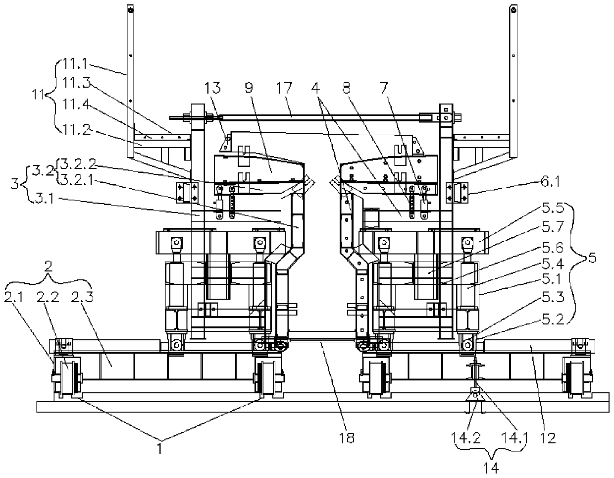
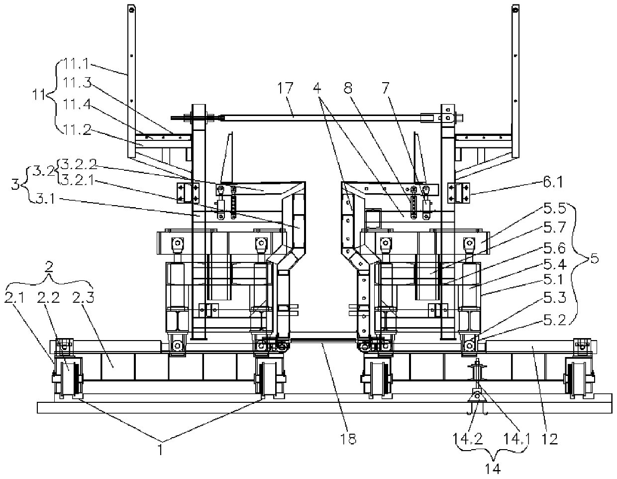
[0059] Such as Figures 1 to 11 As shown, this embodiment provides a special mold for T-shaped beam pouring, including a guide rail 1, on which a walking trolley 2 is slidably arranged to cooperate with it, and the walking trolley 2 is symmetrically provided with a mold for forming a T-shaped beam. The left side mold 3, the right side mold 4 and both ends of the beam 15, the left side mold 3 includes a frame 3.1 and a panel 3.2 detachably connected to the inner side of the frame 3.1, and the walking trolley 2 is provided with a Mold guiding device 5 with high travel space, the mold guiding device 5 can slide left and right, the outer ends of the two frames 3.1 are equipped with a number of flip-type demoulding mechanisms 6 above the mold guiding device 5, and the two frames 3.1 are equipped with automatic slope adjustment Mechanism 7 and locking mechanism 8, the tops of automatic slope adjustment mechanism 7 and locking mechanism 8 are all hinged on the bottom of the rotatable...

Embodiment 2

[0062] Such as Figures 1 to 10 As shown, this embodiment is further optimized on the basis of Embodiment 1. Specifically, two guide rails 1 are correspondingly arranged under the left mold 3 and the right mold 4, and the walking trolley 2 includes several The guide slide seat 2.1 arranged along the length direction of the guide slide track 1 is provided with a drive wheel 2.2 that cooperates with the guide slide track 1, and the corresponding two guide slide seats located under the left mold 3 and the right mold 4 2.1 is connected with a side guide rail 2.3, and the side guide rail 2.3 and the guide rail 1 are perpendicular to each other. The mold guide device 5 includes a traverse car 5.1, and the side guide rails 2.3 are equipped with a horizontal oil cylinder 12 and a piston rod of the horizontal oil cylinder 12. Connected to the bottom of the traversing vehicle 5.1, the four corners of the bottom of the traversing vehicle 5.1 are provided with mounting frames 5.2, and the...

Embodiment 3

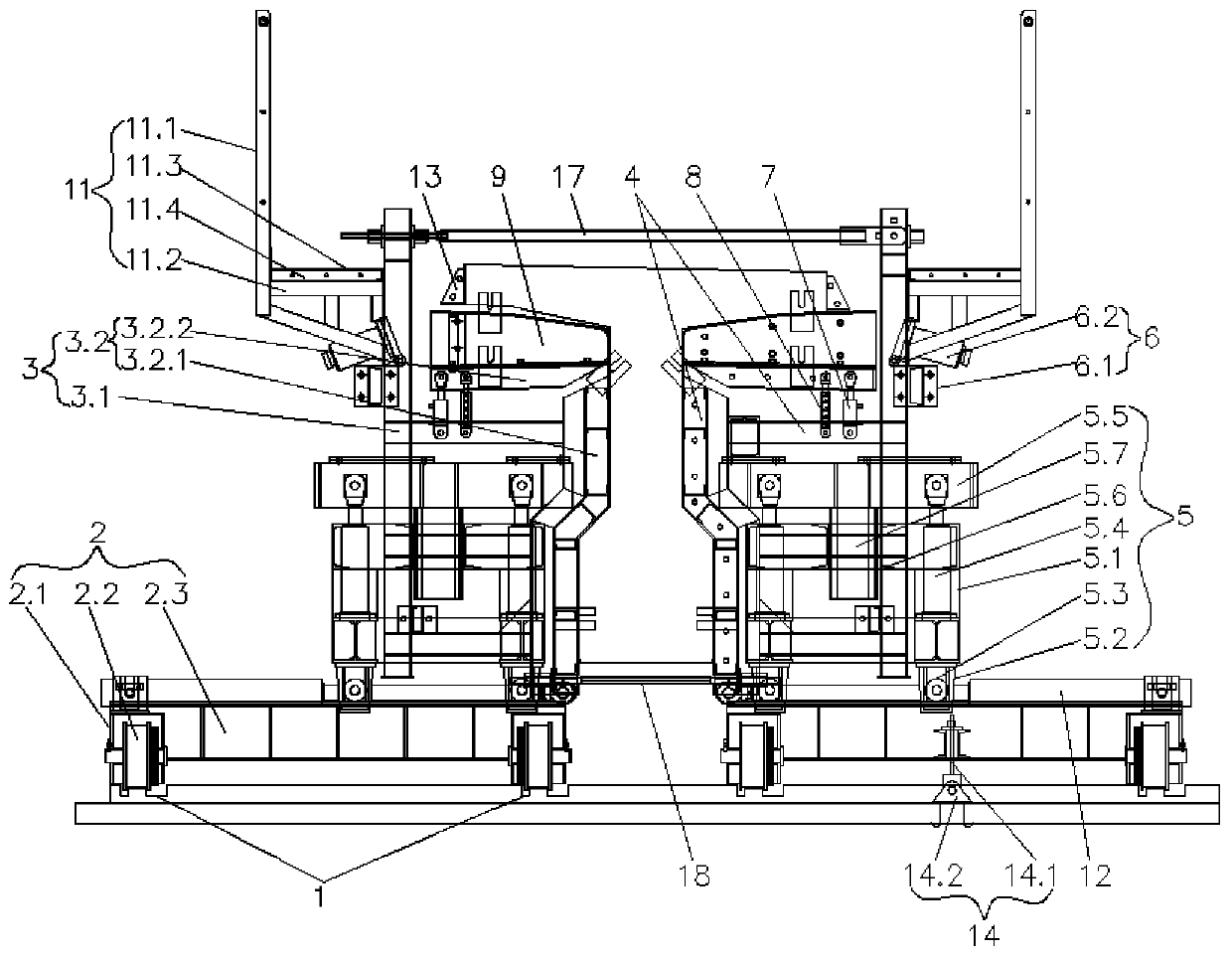
[0065] Such as Figures 1 to 3 As shown, this embodiment is further optimized on the basis of Embodiment 1. Specifically, the flip-type demoulding mechanism 6 includes a base 6.1 arranged on the outer end of the frame 3.1, and an ejection cylinder 6.2 is hinged on the base 6.1. The ejection cylinder 6.2 acts on the rib plate position of the T-beam.

[0066] In this embodiment, when the mold is demoulded, the ejector cylinder acts on the rib plate of the T-beam, and the mold is ejected by using the reverse thrust. When the mold is closed, the ejector cylinder is turned over to the outside of the base to avoid ejection. The oil cylinder collides with steel bars and other components to ensure smooth mold closing.


PUM


Abstract

The invention discloses a T-shaped beam casting special mold and a using method thereof, and relates to the technical field of T-shaped beam manufacturing. The T-shaped beam casting special die comprises a guide rail, wherein a walking trolley is arranged on the sliding rail in a sliding mode, a left mold and a right mold are symmetrically arranged on the walking trolley, the left mold comprises frames and panels connected to the inner side of the frames, the walking trolley is provided with mold guide devices which are positioned at the outer side ends of the two frames and provided with high-stroke spaces, the outer side ends of the two frames are provided with overturning type demolding mechanisms, an automatic slope adjusting mechanism and a locking mechanism are arranged on each frame, the tops of the automatic slope adjusting mechanisms and the tops of the locking mechanisms are hinged to the bottom of rotatable parts of the panels, combined adjusting mechanisms for adjusting theheight of the left mold and the bottom of the right mold are arranged at the bottom of the left mold and the bottom of the right mold, and supporting columns which are convenient to assemble and disassemble are arranged on the outer sides of the tops of the two frames, and during use, the supporting columns are subjected to mold closing and grouting, demoulding. The T-shaped beam casting specialmold has the advantages of being complete in function and good in T-shaped beam forming quality.

Description

technical field [0001] The invention relates to the technical field of T-beam production, and more specifically relates to a special mold for T-beam pouring and a use method thereof. Background technique [0002] With the progress of society and the development of construction technology, the construction technology of T-beam prefabrication in highway and bridge construction has become the main structural form of buildings. T-beam prefabrication is mainly applied to the important load parts of the bridge, and its quality is directly related to the bridge structure. In the construction process, T-beam prefabrication is not only a key link in engineering construction, but also an important prerequisite for ensuring the safety of people's lives and property. Prefabricated T-beams are a relatively common construction technology in engineering bridge construction. Prefabrication with a large span is a relatively complicated process, such as controlling formwork construction, con...

Claims


Application Information

Patent Timeline
Patent Type & Authority Applications(China)
IPC IPC(8): B28B7/02B28B7/12B28B13/02B28B13/06
CPCB28B7/02B28B7/12B28B7/0014B28B13/0215B28B13/06
Inventor 罗龙聪于建
Owner SICHUAN EAST SPRING MACHINERY EQUIP MFG CO LTD
Why Eureka
Try Eureka