Compression bar contact type tensegrity structure and integration and tension exertion method

A tension-integrated structure and contact-type technology, applied in truss-type structures, special data processing applications, instruments, etc., can solve the problems of low rigidity of the tensioned overall structure, difficulty in installation and integration, and difficult tension, etc., and achieve the tension application method Efficient, geometrically stable and easily controlled effects

Active Publication Date: 2019-07-05
SHANGHAI JIAO TONG UNIV +1
View PDF5 Cites 15 Cited by
  • Summary
  • Abstract
  • Description
  • Claims
  • Application Information

AI Technical Summary

Problems solved by technology

[0010] In view of the above-mentioned defects of the prior art, the technical problem to be solved by the present invention is how to solve the problem of low rigidity and poor stability of

Method used


Image

  • Compression bar contact type tensegrity structure and integration and tension exertion method
  • Compression bar contact type tensegrity structure and integration and tension exertion method
  • Compression bar contact type tensegrity structure and integration and tension exertion method

Examples


Embodiment 1

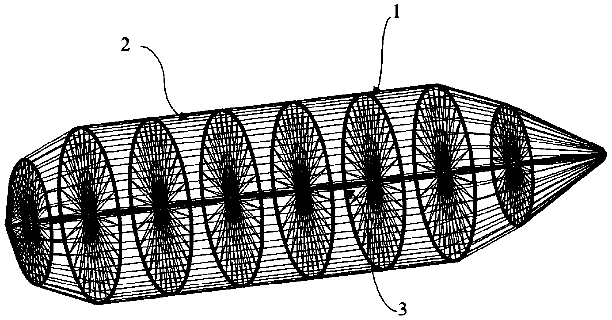
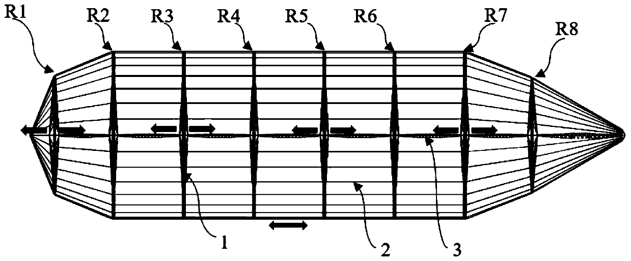
[0042] Such as figure 1 , figure 2 As shown, a preferred embodiment of the present invention provides a three-dimensional schematic diagram of a tension bar contact type tensioned overall structure, which includes a stiffening ring triangular truss 1, a high-strength and high-rigidity longitudinal tie bar 2, a central axis triangular truss 3, and more A stiffening ring triangular truss 1 is isolated under pressure, a plurality of central mandrel triangular trusses 3 are in contact with pressure, and several high-strength and high-rigidity longitudinal tie rods 2 are continuously tensioned to form a self-balancing and self-supporting tensioned overall structure.

[0043] The tensioned overall structure is a combined geometry, the head and tail are conical, the middle section is cylindrical, the middle section of the stiffened ring triangular truss 1 has the same diameter, parallel, and the same spacing, and the stiffened ring triangular truss 1 at both ends has a small diamete...

Embodiment 2

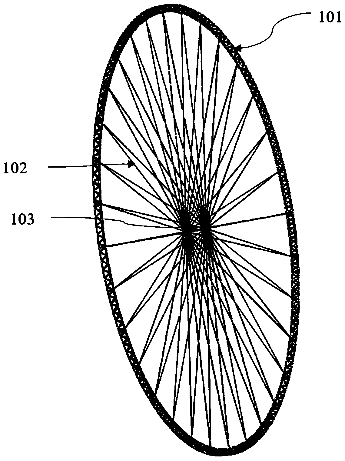
[0058] On the basis of the first embodiment, the high-strength and high-rigidity longitudinal tie rods 2 in the second embodiment are sequentially connected with multiple (5-7) parallel stiffening ring triangular trusses 1 from the outer ring to the tail to form a closed tension ring. The central axis triangular truss 3 is multi-segment (6-8), which are sequentially connected to the hub shafts 103 of multiple (5-7) parallel stiffening ring triangular trusses 1 to form a pressure rod contact type pressure-bearing center from the bow to the stern spindle.


PUM


Abstract

The invention discloses a compression bar contact type tensegrity structure and an integration and tension exertion method, and relates to the technical field of engineering structure. The compressionbar contact type tensegrity structure comprises stiffening ring triangular trusses, core shaft triangular trusses and longitudinal pulling rods. The stiffening ring triangular trusses are pressed inan isolation mode; the core shaft triangular trusses bear pressure in a contact mode; and the longitudinal pulling rods are constantly pulled, and a plurality of paralleled outer rings of the stiffening ring triangular trusses in the heat-to-tail sequence and are closed to tails. The compression bar contact type tensegrity structure is a self-balance and self-bearing structure, segmented assemblage is adopted, the compression bar contact type tensegrity structure symmetrically extends, modules are integrated in an assembly mode, the longitudinal pulling rods are enabled to exert uniform tension through the graded and symmetric synchronized push of ends of the core shaft triangular trusses. The compression bar contact type tensegrity structure and the integration and tension exertion methodhave the characteristics of light weight, high stiffness, high geometric stability, and high practicability; the installation integration method is simple, convenient and safe, and has a high expandability; and the tension exertion method is effective, the tension exertion equipment is less, control is easy, the tension is uniform and precise, and the structural joint is simple and neat.

Description

technical field [0001] The invention relates to the technical field of engineering structures, in particular to a pressure rod contact type tension integral structure and integration and tension application method. Background technique [0002] The tensegrity structure is a self-balancing system composed of dispersed rod units and continuous cable units, which can maintain its own stability only by a reasonable topological structure. Due to its advanced design concept, the tensegrity structure is known as "the structural system of the future", and it is gradually becoming a research hotspot in many fields such as architecture, biomechanics, and aerospace. [0003] The proper noun "tensegrity" was first proposed by American scholar Buckminster Fuller, who combined the words "tensional" and "integrity" into the now widely known noun Tensegrity, which translates into Chinese as tensegrity. The term represents a design concept, that is, "the isolated island of the compression r...

Claims


Application Information

Patent Timeline
IPC IPC(8): B64B1/08B64B1/16E04C3/02G06F17/50
CPCB64B1/08B64B1/16E04C3/02G06F30/15G06F2119/06
Inventor 陈务军胡建辉赵兵王伟志杨钧徐建东
Owner SHANGHAI JIAO TONG UNIV
Why Eureka
Try Eureka