Self-moving flexible belt conveyor
A belt conveyor, self-moving technology, used in conveyors, conveyor objects, transportation and packaging, etc., can solve the problems of low economy and the inability of belt conveyors to unload, achieve high economy, save labor costs and time, The effect of reducing the load
- Summary
- Abstract
- Description
- Claims
- Application Information
AI Technical Summary
Problems solved by technology
Method used
Image

Examples
specific Embodiment approach 1
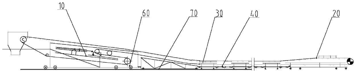
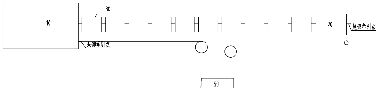
[0017] Specific implementation mode one: combine Figure 1 to Figure 7 Describe this embodiment, a self-moving flexible belt conveyor described in this embodiment, which includes a movable head station 10 and a movable tail station 20, and this embodiment also includes at least two middle movable modules 30, and a plurality of connecting rods parts 40, traction device 50, multiple bottom moving mechanisms 60 and rails 70, the movable head station 10, the movable module 30, and the movable tail station 20 are hinged end to end through a plurality of connecting rods 40, and the movable head station 10, movable The mobile tail station 20 and the middle movable module 30 are all rollingly connected to the track 70 laid on the ground through the bottom moving mechanism 60, and the traction device 50 is connected to the movable head station 10 and the movable tail station 20 respectively through two wire ropes.
[0018] In this embodiment, the movable head station 10, the movable ta...
specific Embodiment approach 2
[0019] Specific implementation mode two: combination Figure 1 to Figure 7 To illustrate this embodiment, a movable head station 10 of a self-moving flexible belt conveyor in this embodiment includes a frame 101, a head funnel 102, a head frame 103, a head roller 104, a reversing roller 105, and a tension roller 106. A plurality of roller groups 107 and hydraulic tensioning device 108, the head funnel 102 and the head frame 103 are installed on the head platform frame 101a at the front end of the frame 101 sequentially from front to back, and the head roller 104 is installed on the head On the frame 103, the reversing roller 105 is installed on the rear end of the frame 101, the hydraulic tensioning device 108 is installed on the middle part of the frame 101, the tensioning roller 106 is installed on the hydraulic tensioning device 108, and a plurality of idler roller groups 107 are installed along the The length direction of the frame 101 is evenly distributed on the upper su...
specific Embodiment approach 3
[0021] Specific implementation mode three: combination Figure 1 to Figure 7 Describe this embodiment, the movable tail station 20 of a self-moving flexible belt conveyor described in this embodiment includes a tail frame 201, a material guide trough 202, a tail frame 203, a tail drum 204 and a tail roller group 205, and the tail frame 203 is installed on the rear end of the tail frame 201, the tail drum 204 is installed on the tail frame 203, the material guide groove 202 is installed on the upper surface of the middle part of the tail frame 201, and a plurality of tail roller groups 205 are installed in sequence from front to back. on the upper surface of the tail frame 201.
[0022] The tail frame 201 is used as the main support mechanism of the movable tail station 20; the material guide trough 202 is installed on the tail frame 201, and is used to constrain the transportation materials from being scattered; the tail frame 203 is installed on the tail frame 201, and is use...
PUM
 Abstract
Description
Claims
Application Information