Combined electric-control high-pressure one-way valve

A high-pressure one-way valve, compound technology, applied in the direction of control valve, sliding valve, valve details, etc., can solve the problems of control piston rod not working, complex structure of hydraulic control check valve, increasing control oil circuit, etc. Remote control, improved frequency response, reduced port effect

Pending Publication Date: 2019-07-05
WUHAN UNIV OF SCI & TECH
View PDF23 Cites 1 Cited by
  • Summary
  • Abstract
  • Description
  • Claims
  • Application Information

AI Technical Summary

Problems solved by technology

There is also an oil discharge port in the control piston rod cavity. If there is no oil discharge port, the control piston rod will not work when the back pressure of the oil return is high.
This kind of hydraulic control check valve has a complex structure and increases the control oil circuit. At the same time, the hydraulic control time is generally longer than the electric control time, and the frequency response is also low.

Method used


Image

  • Combined electric-control high-pressure one-way valve
  • Combined electric-control high-pressure one-way valve
  • Combined electric-control high-pressure one-way valve

Examples


Embodiment 1

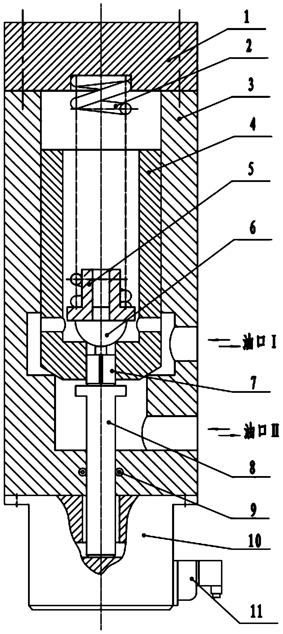
[0033] The utility model relates to a composite electronically controlled high-pressure check valve. This example figure 1 As shown: the one-way valve includes a valve cover 1 , a spring 2 , a valve body 3 , a main valve core 4 , an unloading valve core 6 , an unloading valve core rod 7 , a push rod 8 and an electromagnet 10 .

[0034] Such as figure 1 As shown, the open end of the valve body 3 is fixed with a valve cover 1, and the closed end of the valve body 3 is fixed with an electromagnet 10; the valve body 3 is equipped with a main valve core 4, and the main valve core 4 is sequentially equipped with an unloading valve from the inside to the outside. Core 6, spring seat 5 and spring 2. The lower part of the unloading spool 6 is located at the orifice of the stem through hole of the main spool 4, the spring seat 5 is installed on the upper end surface of the unloading spool 6, one end of the spring 2 is installed on the spring seat 5, and the spring 2 The other end is ...

Embodiment 2

[0049] A composite electronically controlled high-pressure check valve. Except following technical parameter, all the other are with embodiment 1:

[0050] The cone angle of the truncated cone is 35° to 45°;

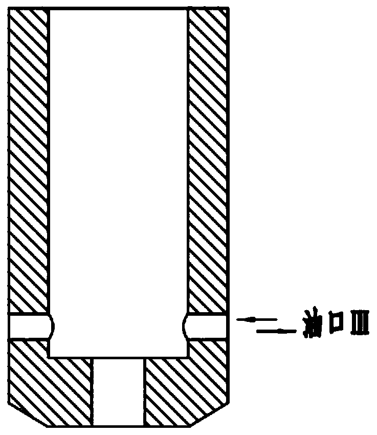
[0051] The inner end of the cavity of the main valve core 4 is provided with four oil ports III along the radial direction;

[0052] The diameter of the short cylinder of the unloading spool 6 is 0.25 to 0.3 times the diameter of the hemisphere;

[0053] The diameter of the small cylinder of the unloading valve core rod 7 is 0.35-0.4 times the diameter of the large cylinder of the unloading valve core rod 7 . Have 4 oil unloading grooves along the prime line direction on the large cylinder surface of unloading spool rod 7.

[0054] The electromagnet 10 is a proportional electromagnet.

[0055] Owing to adopting above-mentioned technical scheme, this embodiment has the following advantages compared with the prior art:

[0056] 1. When the external power supply is con...


PUM


Abstract

The invention relates to a combined electric-control high-pressure one-way valve. According to the technical scheme, an electromagnet (10) is fixed at the closed end of a valve body (3), a main valveelement (4) is arranged in the valve body (3), the main valve element (4) is sequentially provided with an unloading valve element (6), a spring seat (5) and a spring (2) from inside to outside, the upper end of an unloading valve element rod (7) is in contact with the lower portion of the unloading valve element (6), the lower end of the unloading valve element rod (7) penetrates out of a valve rod through hole of the main valve element (4) to be in contact with the upper end of a push rod (8), the lower portion of the push rod (8) passes through a push rod through hole of the valve body (3)to be inserted into a circular hole of the electromagnet (10), an annular sealing ring (9) is arranged on the inner wall of the push rod through hole of the valve body (3), the main valve element (4)is a hollow cylinder with one closed end and one open end, the appearance of the closed end is in a circular truncated cone shape, the valve rod through hole is formed in the closed end along the axis, and 2-4 oil ports III are formed closed to the inner end of a hollow cavity of the main valve element (4) in the radial direction. The combined electric-control high-pressure one-way valve has the characteristics that the automatic control level is high, the structure is simple, the influence of the oil return back pressure is avoided, the response speed is high, and an oil way does not need tobe controlled.

Description

technical field [0001] The invention belongs to the technical field of one-way valves. In particular, it relates to a composite electronically controlled high-pressure check valve. Background technique [0002] At present, it is more common to use one-way valves in hydraulic systems. In high-pressure hydraulic systems, hydraulically controlled one-way valves are used, which can lock high-pressure oil and stop hydraulic cylinders from moving. When the return stroke of the hydraulic cylinder is required, the high-pressure oil must be released and returned to the oil. At this time, the hydraulic control check valve needs to be opened to make the oil flow in the opposite direction. When the hydraulically controlled one-way valve core is opened in reverse, it is difficult to open under the action of high-pressure oil, and when the control piston pushes the check valve core, the oil pressure in the high-pressure circuit is released in a short time, which will Makes a big impact ...

Claims


Application Information

Patent Timeline
Patent Type & Authority Applications(China)
IPC IPC(8): F15B13/02F16K31/06F16K15/02F16K3/30
CPCF15B13/021F16K31/061F16K15/02F16K3/30
Inventor 湛从昌郭媛傅连东陈新元张磊
Owner WUHAN UNIV OF SCI & TECH
Why Eureka
Try Eureka