
Object multi-angle high-speed water entry experiment device controlled by high-pressure gas

An experimental device and multi-angle technology, applied to measuring devices, compressed air guns, fluid dynamics tests, etc., can solve the problems of large water entry angle, injury to experimenters, and high cost, so as to improve the clarity of the picture and ensure safety Effects on sex, freedom of movement

Pending Publication Date: 2019-07-05
HARBIN ENG UNIV
View PDF0 Cites 12 Cited by
  • Summary
  • Abstract
  • Description
  • Claims
  • Application Information

AI Technical Summary

Problems solved by technology

[0004] 1. The speed limit of objects entering the water is relatively large, and it is impossible to simulate high-speed or ultra-high-speed working conditions;
[0005] 2. Only the working condition of a single shape object entering the water at high speed is considered, and the same set of devices is not realized to meet the needs of various water entering conditions;
[0006] 3. There are relatively large restrictions on the angle of entry into the water, and it is impossible to meet the requirements of the entry angle of objects from 0 to 90 degrees;
[0007] 4. The high-speed water entry test of objects generally uses pools, which consumes a lot of money and the physical phenomena recorded by high-speed cameras are not clear;
[0008] 5. After the object enters the water at high speed, the impact of the high-pressure exhaust gas on the free liquid surface is not taken into account, and the real object entering the water cannot be captured;
[0009] 6. Insufficient protection for experimenters and devices, and the existence of high voltage is likely to cause injury to experimenters

Method used


Image

  • Object multi-angle high-speed water entry experiment device controlled by high-pressure gas
  • Object multi-angle high-speed water entry experiment device controlled by high-pressure gas
  • Object multi-angle high-speed water entry experiment device controlled by high-pressure gas

Examples


Embodiment Construction

[0035] The present invention will be further described below in conjunction with the accompanying drawings. It should be understood that the specific implementation examples described here are only used to explain the present invention, and are not intended to limit the present invention.

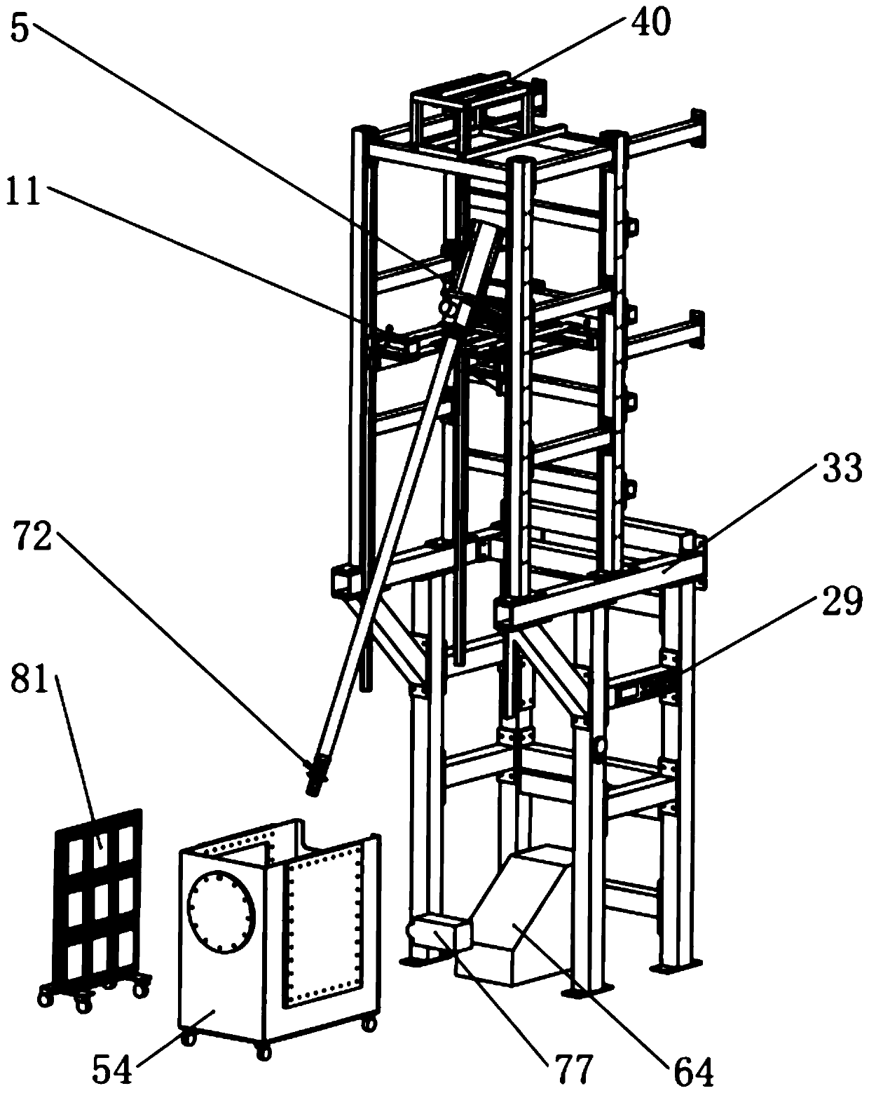
[0036] see figure 1 , figure 1 It is the overall schematic diagram of the patent of the present invention. It is mainly composed of several modules such as bracket, lifting platform, angle adjustment device, launch device, bullet holder collection and deflation device, mobile water tank, array light source and high-speed camera. The following describes each component module in detail.

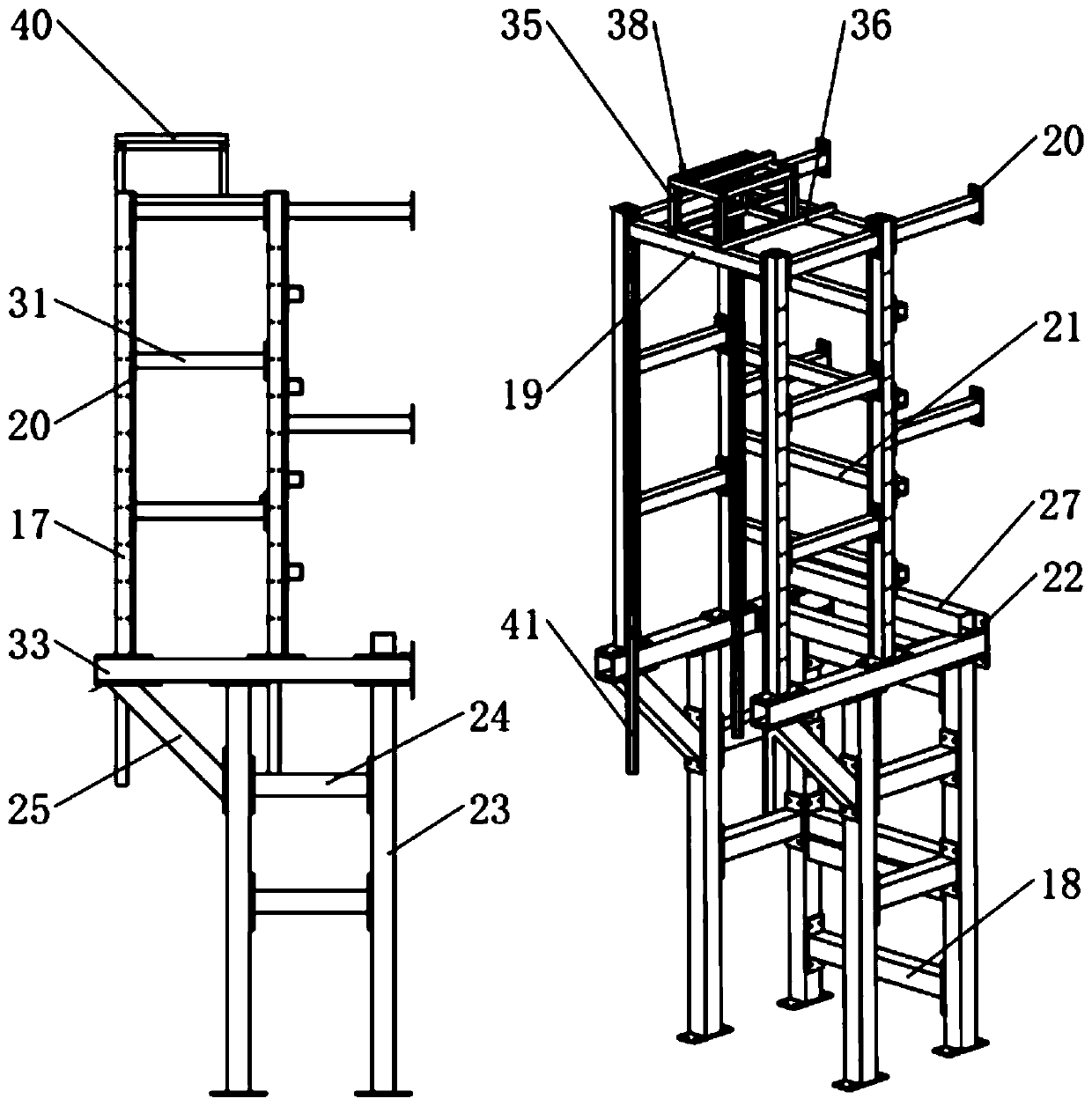
[0037] see figure 2 , figure 2 It is a schematic diagram of the bracket of the patent of the present invention. The support is designed as upper and lower layers. The lower layer is mainly for load bearing and reinforcement. The upper layer is for arranging slide rails 41 and electric hoists 40. The l...


PUM


Abstract

The invention belongs to the object high speed water entry experiment field and especially relates to an object multi-angle high-speed water entry experiment device controlled by a high-pressure gas.In the invention, a same set of device satisfies needs of a plurality of experimental work conditions, the highest water entry speed of an object can be 600m / s, and a water entry angle is 0 to 90 degrees. An emission-object bullet holding device is adopted to clamp an emission object, the emission objects with multiple sizes and shapes can be satisfied, and a bullet holding collector and a deflation device are added at a barrel end of an emission device so as to avoid an influence of the high-pressure gas on a water entry moment of the object. An acceleration sensor is installed in the emission object so as to record an acceleration change process of the object during a water entry process. An array light source makes a water entry process shot by a high-speed camera be clearer so as to satisfy high-precision experiments under different working conditions, and good operability and repeatability are possessed. A manual deflation device is installed on a high pressure gas tank so that manual deflation can be performed, which is safe and reliable. A device structure is compact and flexible and an integral occupied space is small.

Description

technical field [0001] The invention belongs to the field of high-speed water entry experiments. Specifically relates to a multi-angle high-speed water entry experimental device for objects controlled by high-pressure gas. Background technique [0002] The important engineering value of the water entry problem of structures has attracted the attention of domestic and foreign researchers. The water entry of structures is a complicated process, respectively, at low speed and high speed. At present, the research on the problem of water entry at low speed structures is based on experiments and theoretical derivations. Both numerical simulation and numerical simulation have made great progress, but the research on the high-speed water entry of structures has not yet made a breakthrough. Research on high-speed entry of structures into water has gradually become the focus of domestic defense research. [0003] During the process of the structure being injected from the air into t...

Claims


Application Information

Patent Timeline
Patent Type & Authority Applications(China)
IPC IPC(8): G01M10/00F41B11/70F41B11/62F41B11/50F41A21/32F41A21/28
CPCG01M10/00F41B11/62F41B11/50F41B11/70F41A21/32F41A21/28
Inventor 明付仁张阿漫张晓龙王诗平刘云龙刘丙祥崔璞张帅
Owner HARBIN ENG UNIV
Learn More