Standardized machine room dynamic environment monitoring and management system

A dynamic environment monitoring and management system technology, applied in the field of communication management, can solve problems such as air pressure imbalance, burning power supply, insulation resistance drop, etc., to achieve the effect of ensuring internal and external air pressure, reducing pollution surface, and improving cooling

Inactive Publication Date: 2019-07-05
国网安徽省电力有限公司池州市贵池区供电公司
View PDF12 Cites 2 Cited by
  • Summary
  • Abstract
  • Description
  • Claims
  • Application Information

AI Technical Summary

Problems solved by technology

[0003] Dust can be said to be the deadly enemy of the computer room. Because the dust contains moisture and corrosive substances, the insulation resistance between adjacent printed lines will drop, or even short circuit, affecting the normal operation of the circuit. In severe cases, it will burn the power supply, motherboard and other equipment. Components; because the current servers and network equipment generate a lot of heat during operation, in order to dissipate the heat, active cooling methods are usually used to discharge the heat. Due to the small space in the computer room, these devices are usually air-cooled. Heat dissipation, the heat dissipation holes cooperate with the convective air to bring dust into the equipment; and the air pressure inside and outside the computer room is unbalanced, and people walking will cause dust to enter the computer room;
[0004] Most of the existing computer room dust removal management is manual timing processing. This processing method is not only inefficient, but also the operator is easy to carry the external dust into the monitoring computer room, so that there is more dust in the computer room, which cannot meet the environmental standards of the computer room.

Method used


Image

  • Standardized machine room dynamic environment monitoring and management system
  • Standardized machine room dynamic environment monitoring and management system
  • Standardized machine room dynamic environment monitoring and management system

Examples


Embodiment Construction

[0024] In order to make the object, technical solution and advantages of the present invention clearer, the present invention will be further described in detail below in conjunction with the accompanying drawings and embodiments. It should be understood that the specific embodiments described here are only used to explain the present invention, not to limit the present invention.

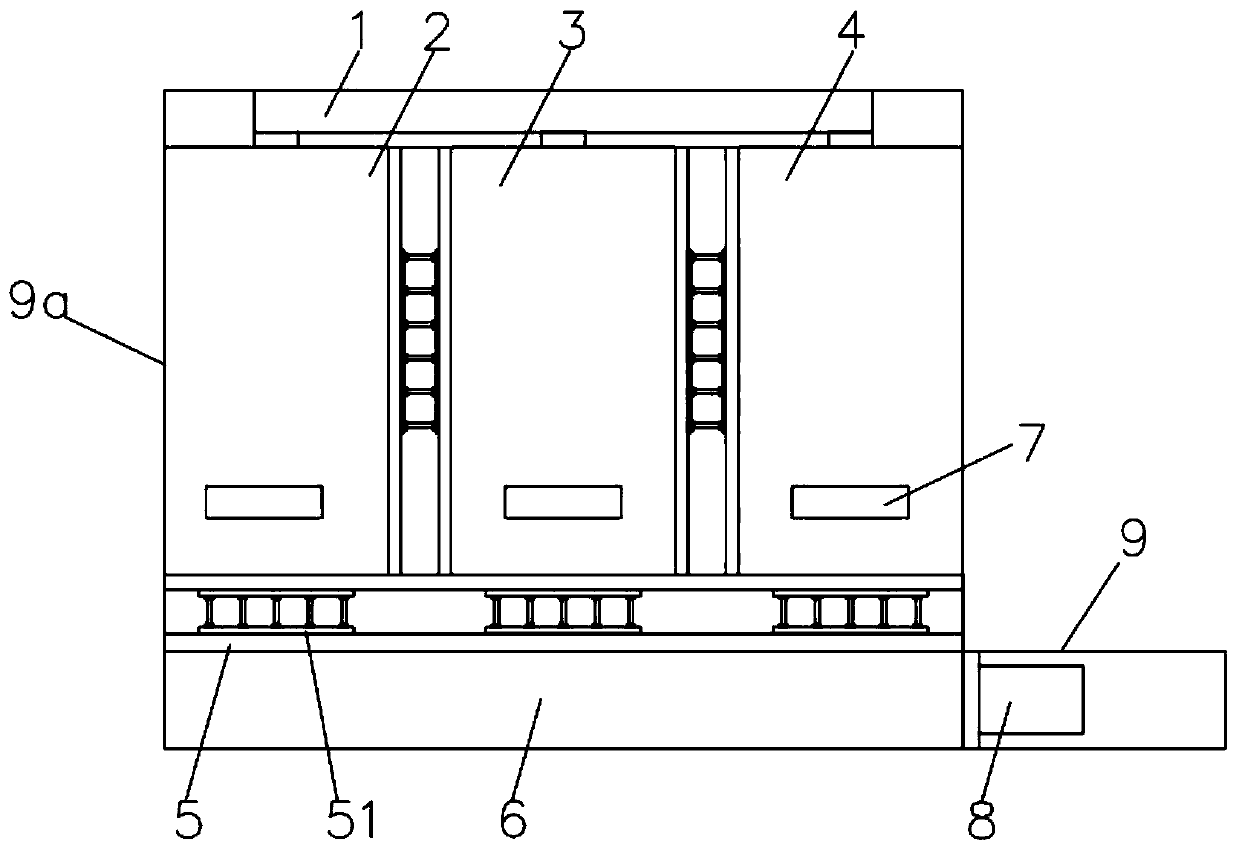
[0025] Such as figure 1 as shown, figure 1 It is an overall schematic diagram of the standardized machine room dynamic environment monitoring and management system described in the present invention;

[0026] The entrance of the main body 9a of the machine room is connected with the entrance and exit channel 9 of the machine room, and the second dust removal module 8 is installed inside the entrance and exit channel 9 of the machine room. Inside;

[0027] The interior of the main body 9a of the machine room is divided into four large areas, which can realize that each module works independently ...


PUM


Abstract

The invention relates to a standardized machine room dynamic environment monitoring and management system, which comprises a machine room main body, wherein the machine room main body comprises a monitoring module, a memory placement module, a server placement module and a power distribution module; the monitoring module, the memory placement module, the server placement module and the power distribution module are electrically connected with one another; the monitoring module, the memory placement module, the server placement module and the power distribution module are divided into independent cavities by means of isolation plates; the monitoring module, the memory placement module, the server placement module and the power distribution module are each internally provided with a data acquisition module, and the data acquisition modules are electrically connected to the monitoring module; and a first dust removal module is installed on the back part of the machine room main body. Thestandardized machine room dynamic environment monitoring and management system can remove dust efficiently while dissipating heat, ensures internal and external pressure to be balance, performs regional management on the interior of the machine room, and prevents dust turbulence.

Description

technical field [0001] The invention relates to a dynamic environment monitoring and management system for a standardized computer room, and belongs to the technical field of communication management. Background technique [0002] With the development of computers and the wide application of networks, more and more units have established their own local area networks, and one of the most important links is the construction of the network center computer room; it not only integrates construction, electrical, installation, network, etc. The integration of multiple professional technologies requires rich experience in project implementation and management; [0003] Dust can be said to be the deadly enemy of the computer room. Because the dust contains moisture and corrosive substances, the insulation resistance between adjacent printed lines will drop, or even short circuit, affecting the normal operation of the circuit. In severe cases, it will burn the power supply, motherboa...

Claims


Application Information

Patent Timeline
Patent Type & Authority Applications(China)
IPC IPC(8): G05B19/042G05D27/02G01D21/02G08B19/00
CPCG05B19/0428G05D27/02G01D21/02G08B19/00G05B2219/2612
Inventor 余平陈刚唐学军丁权方敏朱亚平方明吴文心谢翔陈涛周斌吴联会李峰刘宇熙胡啸坤
Owner 国网安徽省电力有限公司池州市贵池区供电公司
Why Eureka
Try Eureka