Self-maintenance lightning arrester grounding device

A technology of grounding device and arrester is applied in the maintenance of parts of connecting device, coupling device, line connector, etc.

Active Publication Date: 2019-07-05
浙江鸣春纺织股份有限公司
View PDF8 Cites 11 Cited by
  • Summary
  • Abstract
  • Description
  • Claims
  • Application Information

AI Technical Summary

Problems solved by technology

[0004] The above-mentioned authorization documents put forward a good solution to the problem of lightning striking the lightning arrester, but in real life, more lightning rods do not produce lightning protection effects by attracting lightning to the lightning rod, but by keepi

Method used


Image

  • Self-maintenance lightning arrester grounding device
  • Self-maintenance lightning arrester grounding device
  • Self-maintenance lightning arrester grounding device

Examples


Embodiment 1

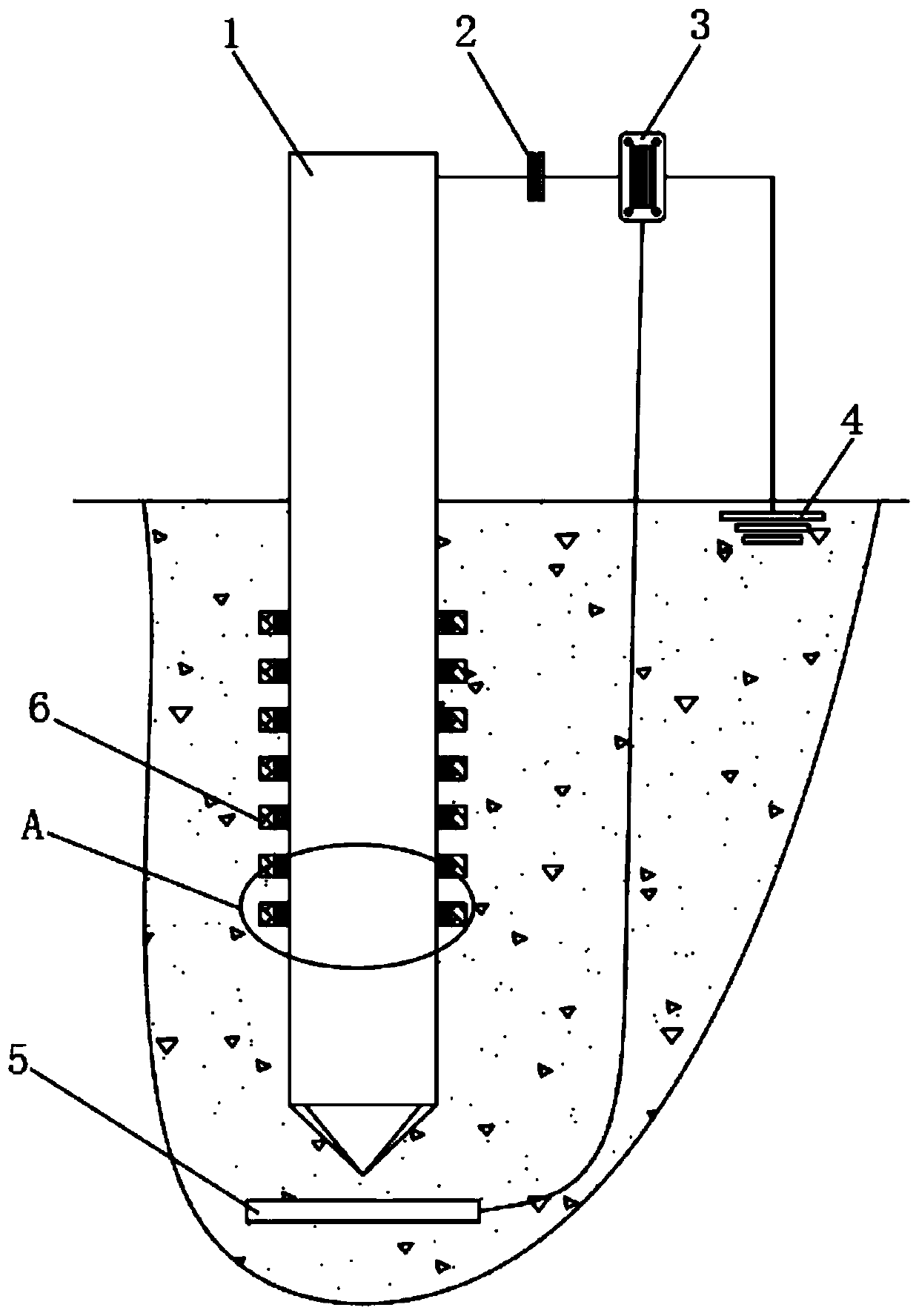
[0023] refer to Figure 1-2 , a grounding device for a self-maintaining lightning arrester, comprising a grounding rod 1, a capacitor plate 2, an electromagnetic relay 3, and a grounding plate 4 inserted on the ground surface, and the grounding rod 1, capacitor plate 2, electromagnetic relay 3, and grounding plate 4 are sequentially connected in series. On the circuit, the grounding piece 4 is grounded, and the part of the grounding rod 1 inserted in the ground is provided with a derusting device; the grounding piece 4 is a metal sheet made of simple chromium, and the cost of simple chromium is relatively high, so only a small amount of chromium is used here. There will be no significant cost increase.

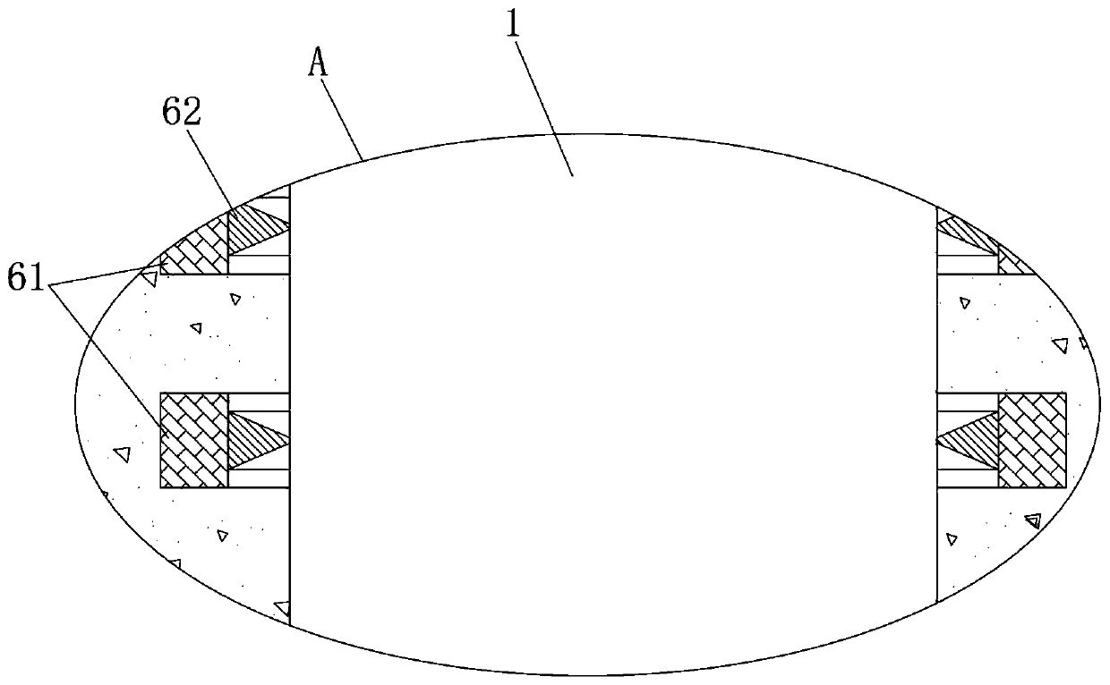
[0024] The derusting device comprises an electromagnet 5 and a plurality of annular scraper groups 6, each annular scraper group 6 includes an annular permanent magnet 61 and a first scraper ring 62, and the first scraper ring 62 is glued and fixed in the annular permanent mag...

Embodiment 2

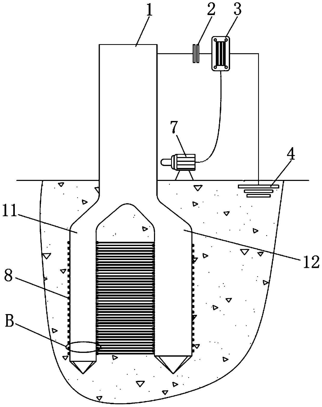
[0029] refer to Figure 3-4 The difference between this embodiment and Embodiment 1 is that the derusting device includes a telescopic motor 7 and a plurality of interactive scraping groups 8, and the part of the ground rod 1 inserted on the ground surface is bifurcated into thin rods 11 and thick rods 12 in a herringbone shape. , each interactive scraping group 8 includes a fixed rod 81 and a second scraper ring 82, several fixed rods 81 are welded equidistantly on the thin rod 11 and the thick rod 12, and each thin rod 11 and the thick rod 12 slide A plurality of second scraper rings 82 are socketed, and the fixed rod 81 on each thin rod 11 is welded to the second scraper ring 82 on the thick rod 12 in one-to-one correspondence, and the fixed rod 81 on each thick rod 12 is connected to the thin rod 11 The second scraper ring 82 on the top is welded one by one, the telescopic motor 7 is fixedly arranged on the ground surface and the output end is opposite to the ground rod 1,...


PUM


Abstract

The invention discloses a self-maintenance lightning arrester grounding device. The self-maintenance lightning arrester grounding device comprises a grounding rod inserted into the ground surface, a capacitor plate, an electromagnetic relay and a grounding piece, wherein the grounding rod, the capacitor plate, the electromagnetic relay and the grounding piece are sequentially connected to one circuit in series, and the grounding piece is grounded; a rust removal device is arranged at the part, inserted into the ground surface, of the grounding rod; the rust removal device comprises an electromagnet and a plurality of annular scraping groups; each annular scraping group comprises an annular permanent magnet and a first scraping ring; and the first scraping ring is glued and fixed on the inner ring of the corresponding annular permanent magnet. The device has the advantages that during thunder and lightning weather, a lightning rod electrically connected with the grounding rod performs point discharge in the cloud layer to enable the grounding rod to have positive charges, and when an oxidation layer outside the grounding rod is more required to be maintained, the electromagnetic relay works for a short time after the capacitor plate is broken down, and the short-time working of the electromagnetic relay drives the rust removal device to remove the oxidation layer of the grounding rod, so that the purpose of free maintenance of the grounding rod is achieved.

Description

technical field [0001] The invention relates to the technical field of power facilities, in particular to a grounding device for a self-maintaining lightning arrester. Background technique [0002] For the current lightning arrester grounding device, a fixed metal rod is generally used, generally made of copper rod, iron rod or alloy rod, which is directly inserted into the ground, and its upper end is connected to the lightning arrester. Due to the harsh underground environment, it is easy to oxidize the surface of the grounding rod and increase the grounding resistance. If this problem is not dealt with in time, the arrester will not be able to protect the electrical equipment normally when a lightning strike occurs. However, the current grounding rod is basically just a fixed homogeneous metal rod. After oxidation, it must be pulled out for repair, or directly replaced with a new grounding rod, and the maintenance cost is relatively high. [0003] After searching, the Ch...

Claims


Application Information

Patent Timeline
IPC IPC(8): H01R4/66H01R13/66H01R13/70H01R43/00
CPCH01R4/66H01R13/665H01R13/70H01R43/002
Inventor 汪金桥
Owner 浙江鸣春纺织股份有限公司
Why Eureka
Try Eureka