Combined low voltage ride-through control system, low voltage ride-through reactive power compensation method and de-excitation control method

A low-voltage ride-through and control system technology, applied in the direction of reactive power adjustment/elimination/compensation, flexible AC transmission system, wind power generation, etc., can solve problems such as reactive power demand, DC side energy accumulation, etc., to solve energy accumulation problems, The effect of solving the problem of low voltage ride through, improving reliability and demagnetization effect

Pending Publication Date: 2019-07-05
HARBIN UNIV OF SCI & TECH
View PDF0 Cites 2 Cited by
  • Summary
  • Abstract
  • Description
  • Claims
  • Application Information

AI Technical Summary

Problems solved by technology

[0004] The present invention overcomes the deficiencies in the prior art above, and provides a combined low-voltage ride-through control system, a low-voltage ride-through reactive power compensation method, and a demagnetization control method. The system and the low-voltage ride-through reactive power compensation method adopt a demagnetization processing method and a The combination of side unloading circuit not only solves the proble

Method used


Image

  • Combined low voltage ride-through control system, low voltage ride-through reactive power compensation method and de-excitation control method
  • Combined low voltage ride-through control system, low voltage ride-through reactive power compensation method and de-excitation control method
  • Combined low voltage ride-through control system, low voltage ride-through reactive power compensation method and de-excitation control method

Examples


specific Embodiment approach 1

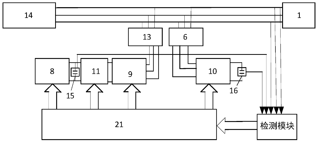
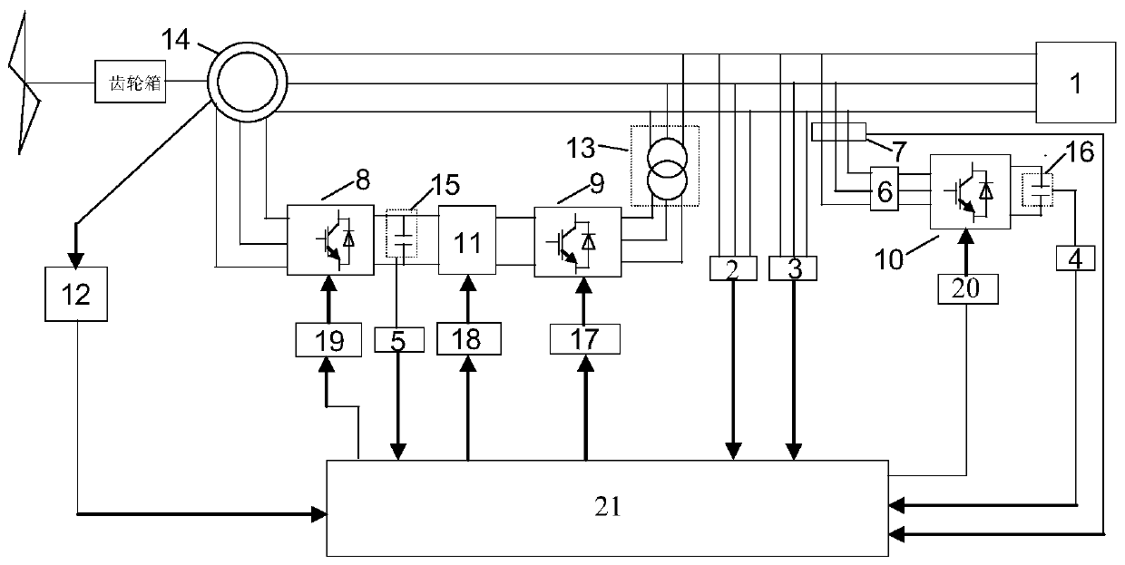
[0055] A combined low-voltage ride-through control system, such as figure 1 As shown, it includes three-phase power grid 1, reactor 6, rotor-side converter 8, grid-side converter 9, STATCOM main circuit 10, DC side unloading circuit 11, grid-side transformer 13, double-fed induction motor 14, second A DC capacitor 15, a first DC capacitor 16, and a main control module 21; the STATCOM main circuit 10 is a static synchronous compensator, and the three-phase grid 1 is connected to a reactor 6, a grid-side transformer 13, a double-fed induction motor 14, and The detection module is connected, the reactor 6 is connected with the STATCOM main circuit 10, and the STATCOM main circuit 10 is respectively connected with the first DC capacitor 16 and the main control module 21, and the first DC capacitor 16 is connected with the detection module, and the The detection module is connected to the second DC capacitor 15, the output end of the detection module is connected to the main contro...

Embodiment approach 1

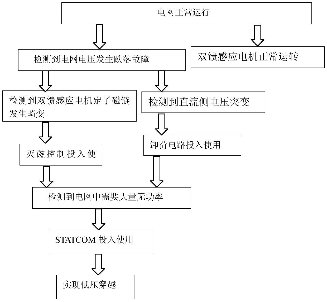
[0064] A low-voltage ride-through reactive power compensation method based on the combined low-voltage ride-through control system described in the first embodiment, such as image 3 shown, including the following steps:

[0065] Step a1, the three-phase grid 1 is powered on, and the three-phase grid 1 operates normally;

[0066] Step a2, judge in real time whether the voltage drop of the three-phase grid 1 has a fault, if not, the doubly-fed induction motor 14 operates normally, and continue to execute step a2; if so, execute step a3;

[0067] Step a3, respectively collecting the current and voltage of the three-phase grid 1 when a fault occurs through the detection module; detecting whether the stator flux linkage of the doubly-fed induction motor 14 is distorted, and whether the DC side voltage has a sudden change;

[0068] Step a4: Send the voltage and current at the time of the fault to the main control module 21 for processing and demagnetization control processing. Aft...

specific Embodiment approach 3

[0072] A specific method based on the demagnetization control process described in the second step a4 of the specific embodiment, such as Figure 4 to Figure 8 shown, including the following steps:

[0073] Step b1, according to the working principle of the doubly-fed induction motor 14, the basic equation of the voltage flux linkage of the rotor and the stator is obtained, as follows:

[0074]

[0075] where u s and u r are stator voltage and rotor voltage respectively, R s and R r Indicates the stator and rotor resistance, ψ s and ψ r are stator flux linkage and rotor flux linkage respectively, i s and i r Expressed as stator current and rotor current, L s and L r are stator inductance and rotor inductance respectively, L m for mutual inductance;

[0076] Step b2, carry out Parker transformation to formula (1), and convert it to the equation under the synchronously rotating dq coordinate system, as follows:

[0077]

[0078] where u sq , u sd i sq i sd ...


PUM


Abstract

The invention relates to a combined low voltage ride-through control system, a low voltage ride-through reactive power compensation method and a de-excitation control method, and belongs to the technical of wind power generation. Overcurrent occurs at the rotor side when the grid voltage has a drop fault, the output power of a grid-side converter is limited, and the accumulation of energy at the DC side will result in voltage rising at the DC side, which main damage DC-side capacitors and power devices. The system and the low voltage ride-through reactive power compensation method are combinedwith a DC-side unloading circuit by adopting the de-excitation control method. The de-excitation control method enhances the de-excitation control effect by adopting a three-step prediction method, not only solves the low voltage ride through problem of a doubly-fed wind power generation system when the grid breaks down, but also solves the problem of energy accumulation at the DC side, applies an STATCOM main circuit and solves the problem of reactive power demand of a doubly-fed induction motor in asynchronous operation.

Description

technical field [0001] The invention belongs to the technical field of wind power generation, and in particular relates to a combined low-voltage ride-through control system, a low-voltage ride-through reactive power compensation method, and a demagnetization control method. Background technique [0002] Energy is an important material basis for human survival and development. With the rapid development of the economy, human consumption of energy is increasing year by year. Conventional energy is facing an increasingly depleted dilemma. Fully developing and utilizing clean energy is the only choice to solve energy problems. . As a new energy source, wind energy has the characteristics of inexhaustible, inexhaustible, pollution-free, and renewable, which makes wind power generation the most mature, largest-scale development, and best commercialization among new energy generation technologies. The way of power generation has been widely valued by countries all over the world....

Claims


Application Information

Patent Timeline
IPC IPC(8): H02J3/38H02J3/18
CPCH02J3/1835H02J3/386Y02E10/76Y02E40/10
Inventor 李文娟张琦乜春颖李玖云
Owner HARBIN UNIV OF SCI & TECH
Why Eureka
Try Eureka