Eureka AIR delivers breakthrough ideas for toughest innovation challenges, trusted by R&D personnel around the world.

A DC power spring topology and its control method

A control method and technology of electric springs, applied in control/regulation systems, DC power input conversion to DC power output, electrical components, etc., can solve problems such as unfavorable large-scale popularization and application, achieve high practical value and application prospects, and enhance Reliability and burden reduction effect

Active Publication Date: 2020-11-20
SOUTHEAST UNIV
View PDF4 Cites 0 Cited by
  • Summary
  • Abstract
  • Description
  • Claims
  • Application Information

AI Technical Summary

Problems solved by technology

More importantly, so far, there has been no way to change DCES in series with DC non-critical loads, which is contrary to the traditional connection method of the power system and is not conducive to large-scale promotion and application

Method used


Image

  • A DC power spring topology and its control method
  • A DC power spring topology and its control method

Examples


Embodiment Construction

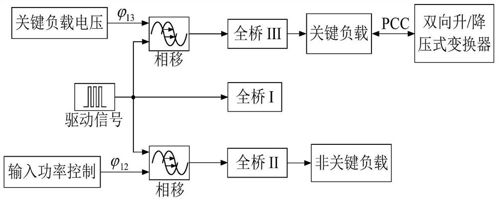
[0020] Such as figure 1 As shown, 1 in the DC power spring topology system structure diagram is a three-port DC / DC converter, 1.1 to 1.3 are the full-bridge circuit I, full-bridge circuit II and full-bridge circuit III inside the three-port converter, and 1.4 is the three-port Transformer, 1.5-1.7 are inductance L1, inductance L2 and inductance L3, 1.8-1.10 is the filter capacitor of each port, 1.11 is the battery pack, 1.12 is the bidirectional DC / DC converter, 1.13 is the filter capacitor, 1.14 is the key load, 1.15 is the non-critical load, and 1.16 is the input terminal of new energy power generation.

[0021] Such as figure 1 As shown, the DC power spring topology includes a three-port DC / DC converter, and the three-port DC / DC converter includes three full-bridge circuits, namely full-bridge circuit I, full-bridge circuit II and full-bridge circuit III, each One output terminal of each full-bridge circuit is correspondingly connected with a filter inductance, which are ...


PUM


Abstract

The invention discloses a DC power spring topology and a control method thereof. The DC power spring topology integrates a three-port converter and a bidirectional DC converter, and each port of the three-port DC / DC converter is connected in parallel with a filter capacitor and a full-bridge converter, one output end of each full-bridge converter is connected with a filter inductor, and each filter inductor is connected in series with a corresponding winding of a three-port transformer; wherein the three-port DC / DC converter Port I is connected in parallel with the output end of new energy power generation, and port II is connected with non-critical load R NC In parallel, Port III is on the one hand with the critical load R C Parallel connection is also connected in parallel with one end of the bidirectional DC / DC converter, and the other end of the bidirectional DC / DC converter is connected to the battery pack. The invention can avoid the series connection of non-critical loads and DC power springs, thereby effectively solving the common defects of current power spring topologies.

Description

technical field [0001] The invention relates to a DC power spring topology applied to a microgrid. Background technique [0002] In recent years, the energy crisis and environmental pollution problems have become increasingly prominent. The development of new energy has been put on the agenda of various countries. The technology of new energy power generation has been continuously improved, especially the wind power industry is advancing by leaps and bounds. Compared with the large power grid, the microgrid is a new power generation and distribution system established by integrating various distributed power generation resources through various smart devices. It is an autonomous system that can realize self-control, protection and management. It can be operated in parallel with the external grid or isolated. [0003] With the increasing load demand in the electrical field and the reduction of fossil fuels, the development and utilization of new energy is imminent. New ener...

Claims


Application Information

Patent Timeline
Patent Type & Authority Patents(China)
IPC IPC(8): H02M3/158
CPCH02M3/1584H02M1/009
Inventor 王青松左武坚程明
Owner SOUTHEAST UNIV
Why Eureka
Eureka Blog
Learn More