
Aircraft movable airfoil adjustment detection system and method

A detection system and movable wing technology, which is applied in the field of adjustment and detection systems for movable airfoils, can solve problems such as affecting aircraft production and manufacturing progress, relying on manual operation experience, increasing aircraft manufacturing costs, etc., and achieves safe and reliable testing, high degree of automation, Simple and easy-to-use effects

Pending Publication Date: 2019-07-09
XIAN AIRCRAFT IND GROUP
View PDF0 Cites 3 Cited by
  • Summary
  • Abstract
  • Description
  • Claims
  • Application Information

AI Technical Summary

Problems solved by technology

Since only the wings of the aircraft, the movable surface of the empennage, the actuators of each movable surface and the position sensor of the rudder surface are installed in the part-installation stage, and the related computer products in the flight control system are not installed, the telex control mode cannot be used To carry out the adjustment and inspection of the movable airfoil, the actuator can only be in the damping working mode, and the deflection of the rudder surface is carried out by manually loading the external force. This method relies too much on manual operation experience. damage, increasing aircraft manufacturing costs
The second method is: after the wing and empennage are installed, go directly to the final assembly stage of the aircraft. After the finished flight control system and the airborne cables are all installed, use the fly-by-wire control mode to carry out the adjustment and inspection of the movable wing surface. If the movable wing surface adjustment If the test fails, it needs to go back to the partial assembly stage for reassembly and then proceed to the final assembly test. Counterattacks in the assembly steps will seriously affect the production progress of the aircraft

Method used


Image

  • Aircraft movable airfoil adjustment detection system and method
  • Aircraft movable airfoil adjustment detection system and method
  • Aircraft movable airfoil adjustment detection system and method

Examples


Embodiment Construction

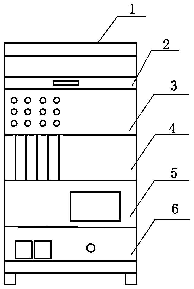
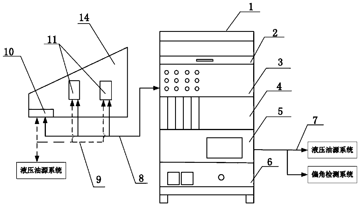
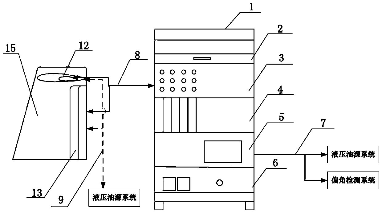
[0027] Such as figure 1 As shown in -3, the aircraft movable wing surface adjustment detection system 1 includes a signal conditioning box 3, a card insertion box 4, an integrated control computer 5, a program-controlled power supply 6, a display 2 and supporting cables 8.

[0028] The rear panel of the signal conditioning box 3 is distributed with an array of sockets, and the signal cross-linking and adaptation are performed between the airfoil actuators, the rudder surface position sensor, the card insertion box 4, and the integrated control computer 5 through the supporting cables 8, Each socket is designed as an error-proof socket and made with a silk screen mark. The front panel of the signal conditioning box 3 is distributed with an array of disconnection blocks, and the inside of the signal conditioning box is provided with a core wire harness, which leads the signal from the rear panel to the disconnection block on the front panel. The block is convenient for fault loc...


PUM


Abstract

The invention discloses an aircraft movable airfoil adjustment detection system and method. The system includes a signal conditioning box, a board card plug-in box, an integrated control computer, a programmable power supply, a displayer and a matched cable. The signal conditioning box is used for fault positioning and metering of the aircraft movable airfoil adjustment detection system, the matched cable is connected with the signal conditioning box and actuators and control plane position sensors on the airfoils and emages, the board card plug-in box provides a required excited signal to drive the actuators to do concertina movement after a work command is adjusted, and the integrated control computer sends an operating personnel command through a human-computer interaction interface tocontrol the movable airfoils to move and feeds back the motion states of the airfoils to a software interface, so that adjustment and detection of secondary airfoils, spoilers, secondary airfoil position sensors, an elevator, a rudder and an elevator position sensor are completed.

Description

technical field [0001] The invention relates to an aircraft movable wing surface testing technology, in particular to a system and method for adjusting and detecting the movable wing surface in the assembly stage of aircraft components. Background technique [0002] The movable wing surface of the aircraft refers to the wing surface on the wing and tail that can be controlled by manipulation, mainly including elevators, ailerons, rudders, spoilers, etc. The fly-by-wire flight control system realizes the aircraft by manipulating the deflection of each movable wing surface of the aircraft. The control of attitude and heading, and the change of small parameters on the wing surface will affect the flight attitude, so the movable wing surface is an important part related to the flight safety of the aircraft. [0003] In the production stage of the aircraft, due to factors such as manufacturing and assembly processes, there will be a certain cumulative error. If the adjustment and...

Claims


Application Information

Patent Timeline
IPC IPC(8): B64F5/60
CPCB64F5/60
Inventor 毛绍婧宋西民鹿凡超王凯张磊磊
Owner XIAN AIRCRAFT IND GROUP
Learn More