
Motor hydrostatic test tank used for deep well submersible electric pump

A submersible electric pump, hydraulic test technology, applied in the application of stable tension/pressure to test the strength of materials, the test of mechanical parts, the test of machine/structural parts, etc. Problems such as poor working environment for personnel and inability to adjust the test pressure to achieve the effect of improving test conditions and efficiency, uniform force and good sealing effect

Inactive Publication Date: 2019-10-15
HEFEI HAICHUAN PETROCHEM EQUIP
View PDF13 Cites 1 Cited by
  • Summary
  • Abstract
  • Description
  • Claims
  • Application Information

AI Technical Summary

Problems solved by technology

Among them, whether the motor, the core component of the deep well submersible electric pump for mining equipment, can withstand such a working environment is a key issue in the development of this equipment. In order to test the reliability of this type of motor, it is necessary to provide a high-voltage, In the experimental sites where the working environment of sewage is similar, the existing experimental method is to conduct tests in abandoned mines. This method is not only time-consuming and laborious, but also the test pressure cannot be adjusted. good
Therefore, it is necessary to provide a container device for the simulation experiment of the motor in the deep well. During the experiment, the motor needs to be placed in the pressure vessel, and the connecting cable of the motor needs to extend out of the pressure vessel, and the connecting cable passes through the sealing ring It is sealed with the pressure vessel. When the pressure in the tank reaches 20MPa (equivalent to 2000 meters underwater), the cable and the top cover cannot be completely sealed, resulting in a large pressure drop rate, which is not conducive to the continuous pressure maintenance of the experimental pressure.

Method used


Image

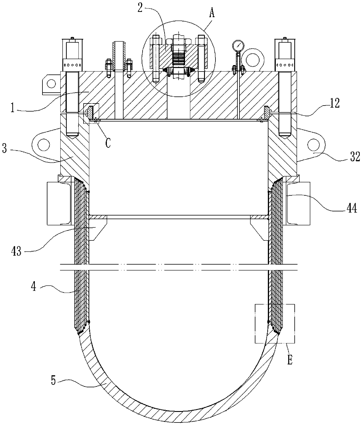
  • Motor hydrostatic test tank used for deep well submersible electric pump
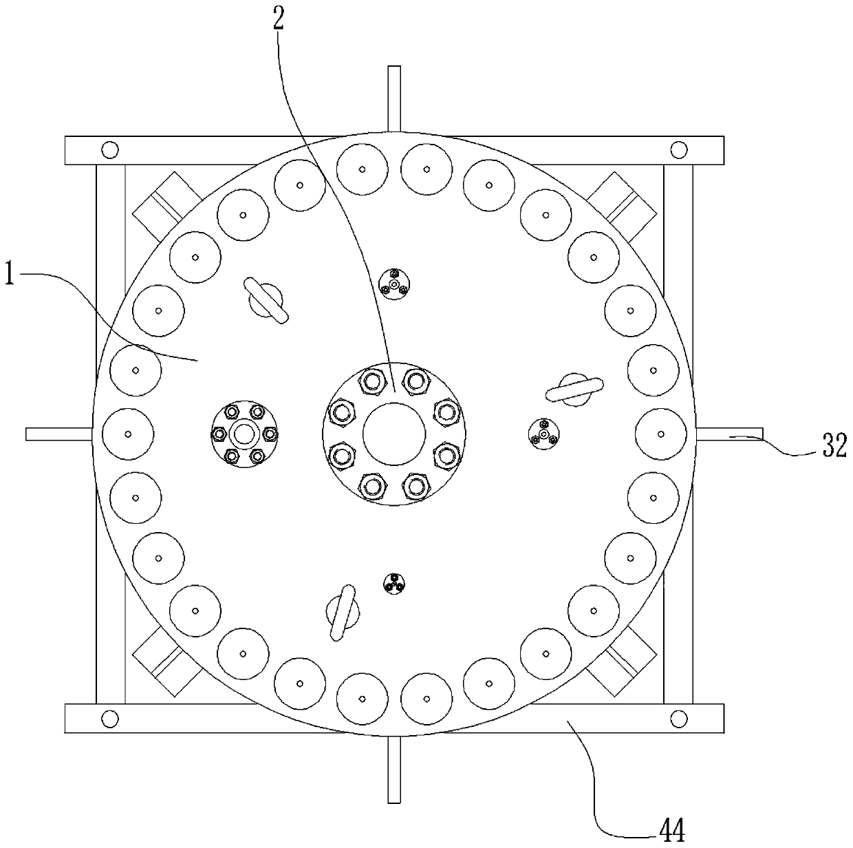
  • Motor hydrostatic test tank used for deep well submersible electric pump
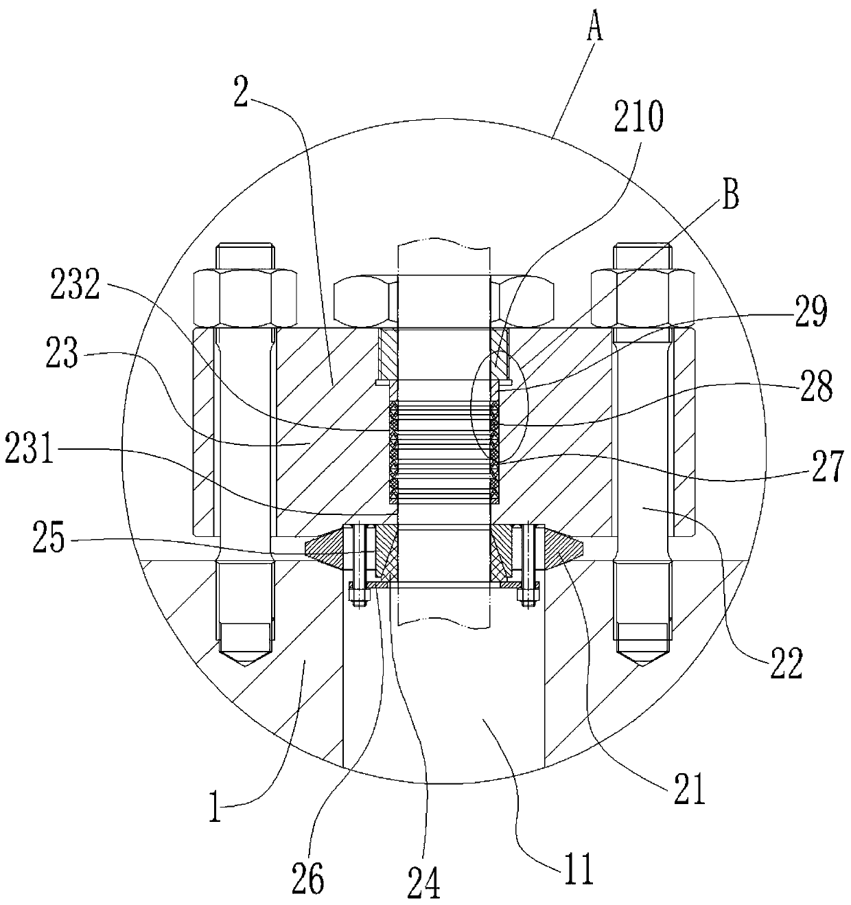
  • Motor hydrostatic test tank used for deep well submersible electric pump

Examples


Embodiment Construction

[0027] It should be understood that the specific embodiments described here are only used to explain the present invention, not to limit the present invention.

[0028] The technical solutions in the embodiments of the present invention will be clearly and completely described below in conjunction with the accompanying drawings in the embodiments of the present invention. Obviously, the described embodiments are only part of the embodiments of the present invention, not all implementations example. Based on the embodiments of the present invention, all other embodiments obtained by persons of ordinary skill in the art without creative efforts fall within the protection scope of the present invention.

[0029] It should be noted that all directional indications (such as up-down-left-right-front-back...) in the embodiments of the present invention are only used to explain the relationship between the components in a certain posture (as shown in the accompanying drawings). If th...


PUM


Abstract

The invention discloses a motor hydrostatic test tank used for a deep well submersible electric pump, and relates to the pressure container technical field. The motor hydrostatic test tank comprises atop cover, which is provided with a cable sealing connector. The cable sealing connector comprises a lens pad, a stud bolt, a blind plate, a conical pad, a conical base and a supporting plate. The middle part of the top cover is provided with a first through hole for passing through a cable of an experimental motor, and the lens pad is arranged between the first through hole and a conical sealingsurface on the blind plate. The upper end of the conical base is fixedly connected with the lower end of the blind plate in a sealed manner, and the middle part of the conical base is provided with the conical pad, and in addition, the conical pad is attached to the conical base through the conical surface, and the conical pad is used to form sealed cooperation between the outer surface of the cable and the blind plate, and the lower part of the conical pad is provided with the supporting plate. The invention is advantageous in that the working environment (high pressure) of the motor for coal mine or other deep well operations is simulated so as to test the performance of the motor, and the sealing performance of the conical pad and the outer surface of the cable are improved.

Description

Technical field: [0001] The invention relates to the technical field of pressure vessels, in particular to a motor hydraulic pressure test tank for a deep well submersible electric pump. Background technique: [0002] The deep well submersible electric pump is a water lifting tool that is directly connected with the motor and the water pump and submerged into the water. It is suitable for material extraction from deep water wells, hot water wells and oceans, and can also be used for material extraction in rivers, reservoirs, canals, etc. [0003] Deep well submersible electric pumps are used in mining equipment used in underground operations in coal mines or other mines to extract underground materials. Due to the harsh working environment, complex underground structures, and deep water, the performance requirements for mining equipment are extremely high. Among them, whether the motor, the core component of the deep well submersible electric pump for mining equipment, can ...

Claims


Application Information

Patent Timeline
Patent Type & Authority Applications(China)
IPC IPC(8): G01M13/00G01N3/12
CPCG01M13/00G01N3/12
Inventor 钱建平
Owner HEFEI HAICHUAN PETROCHEM EQUIP
Learn More