Power monitoring and energy saving system

An energy-saving system and electric energy technology, applied in collectors, electric vehicles, electrical components, etc., can solve the problem that power products cannot set constant parameter values, battery products cannot be used for charge and discharge tests, and grid-connected inverter power supplies have no current equalization Function and other issues

CN101841161AInactive Publication Date: 2010-09-22CHANGZHOU WUJIN FENGTAI ELECTROMECHANICAL
1 Cites 1 Cited by

Patent Information

Authority / Receiving Office
CN · China
Patent Type
Applications(China)
Current Assignee / Owner
Publication Date
2010-09-22
Estimated Expiration
Not applicable · inactive patent

Smart Images

  • Figure 1
    Figure 1
  • Figure 2
    Figure 2
  • Figure 3
    Figure 3
Patent Text Reader

Abstract

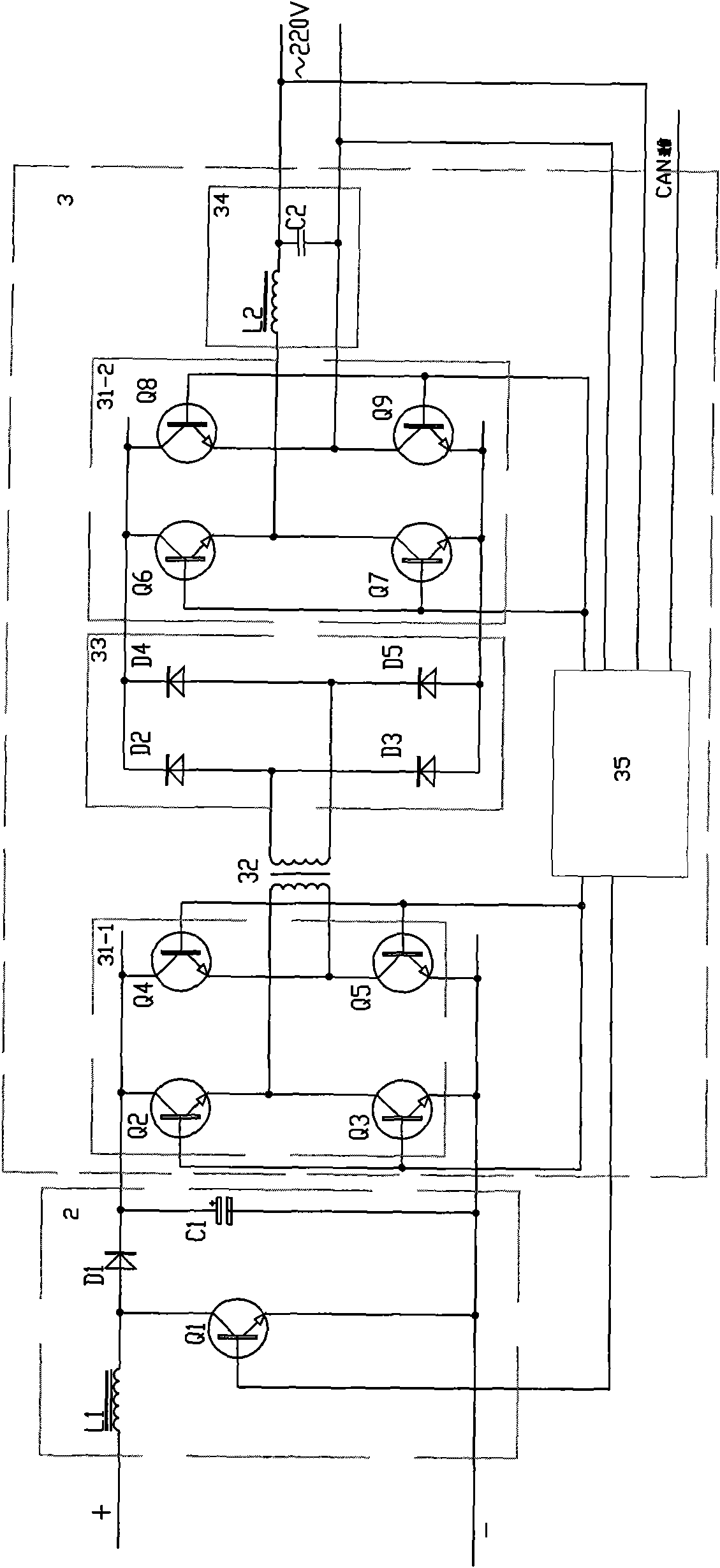
The invention discloses a power monitoring and energy saving system which comprises a discharging circuit module and a grid-connected inverting circuit module, wherein the grid-connected inverting circuit module comprises a high-performance DSP (Digital Signal Processing) main board; the input end of the discharging circuit module is connected into the input end of the grid-connected inverting circuit module, and the output end of the grid-connected inverting circuit module is connected into a power grid; the discharging circuit module comprises an LC filtering circuit consisting an inductor L1 and a capacitor C1 and a power pipe Q1; and the power pipe Q1 and an inverting circuit are both controlled by the high-performance DSP main board. The LC filtering circuit is adopted in the discharging module and can obtain constant current and voltage; and when in use, the system can run in a constant current, resistance and power state just by setting the power supply ageing condition of the system and the current, resistance and power of a storage battery in a charging and discharging test, calculating and analyzing a set parameter by the high-performance DSP main board and outputting a corresponding parameter value for controlling conduction or interruption of the power pipe.
Need to check novelty before this filing date? Find Prior Art

Description

technical field

[0001] The invention relates to a power supply product aging and charging and discharging testing system for storage battery products, in particular to an electric energy monitoring and energy saving system for charging and discharging testing of chargers, adapters, switching power supplies and storage battery products. Background technique

[0002] Before leaving the factory, electronic products such as power supplies usually need to be aged for a certain period of time in order to stabilize their performance. This can eliminate early failure products, which is an important means of quality control of power supplies.

[0003] Power aging is to make power products work under a certain temperature, input voltage, and load current environment. The aging of power supply products in industries such as chargers, adapters, and switching power supplies is carried out by traditional resistance load simulation. This aging method is relatively simple in principle: whe...

Examples

Embodiment 1

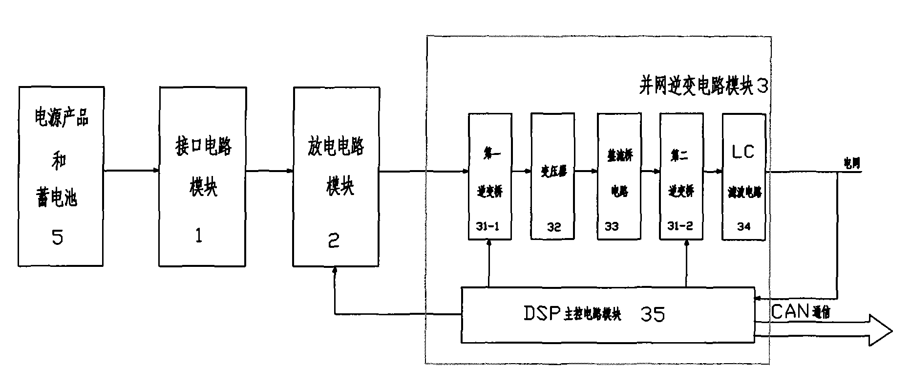
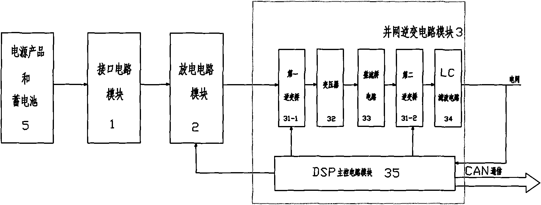
[0026] See figure 1 , the aging of power supply products and the charge and discharge test system of storage battery products in this embodiment include an interface circuit module 1, a discharge circuit module 2, a grid-connected inverter circuit module 3 and a CAN bus-based monitoring circuit module (not shown in the figure). The grid-connected inverter circuit module 3 includes a first inverter bridge 31 - 1 , a transformer 32 , a rectifier bridge circuit 33 , a second inverter bridge 31 - 2 , an LC filter circuit 34 and a high-performance DSP main board 35 . The input end of the interface circuit module 1 is connected to the power supply product and the battery 5, the output end of the interface circuit module 1 is connected to the input end of the discharge circuit module 2, and the output end of the discharge circuit module 2 is connected to the input end of the grid-connected inverter circuit module 3 , the output end of the grid-connected inverter circuit module 3 is c...