Power factor compensation device for connected furnaces

A power factor compensation, body furnace technology, applied in reactive power compensation, reactive power adjustment/elimination/compensation, circuit devices, etc., can solve the problems of three-phase power supply current imbalance, static capacitance compensation can not be compensated, inductive and other problems

Pending Publication Date: 2019-07-09
ANHUI YONGJIE COPPER
View PDF0 Cites 0 Cited by
  • Summary
  • Abstract
  • Description
  • Claims
  • Application Information

AI Technical Summary

Problems solved by technology

[0003] Although the use of the double-coil power frequency induction conjoined furnace has many advantages, there are still several technical problems in the process of using the double-coil power frequency induction conjoined furnace. The double-coil power frequency induction conjoined furnace is In the use of the power supply system, due to the characteristics of its double coils, the congenital phase imbalance of the three-phase power supply current is caused, and the nature of the coils is inductive. The existing technologies such as figure 1 , 2 as shown, figure 2 for figure 1 The schematic diagram of the deformation of the wiring structure diagram. Therefore, a set of compensation capacitors is installed on the three-phase power supply of the melting and casting equipment. The current balance and reactive power compensation are performed by using two-phase switching capacitors at the same time. After a certain number of capacitors are dynamically switched and compensated, However, since the melting and casting equipment has two relatively independent working environments in the actual operation, the melting furnace area and the holding furnace area, it is necessary to continuously adjust the voltage gear, so that the static capacitance compensation cannot be well adjusted with the working state of the melting and casting equipment. The corresponding compensation is made for the change, so that the power factor of the power supply is sometimes low or overcompensated

Method used


Image

  • Power factor compensation device for connected furnaces
  • Power factor compensation device for connected furnaces
  • Power factor compensation device for connected furnaces

Examples


Embodiment Construction

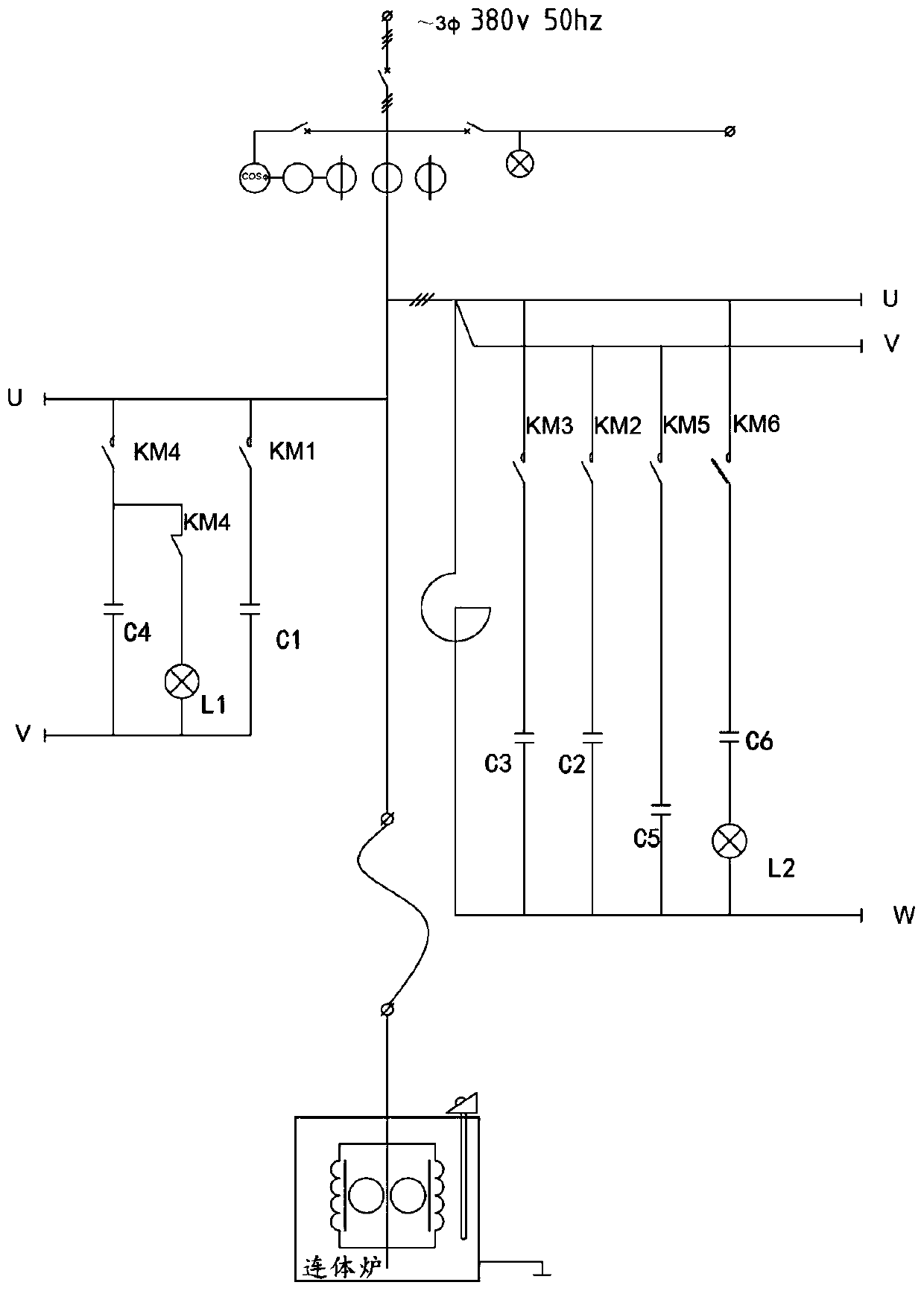
[0018] The specific implementation manner of the present invention will be described in further detail below through the description of the best embodiment with reference to the accompanying drawings.

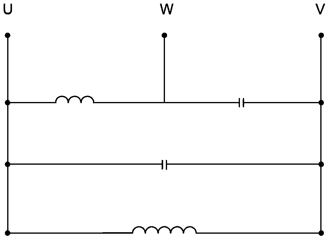
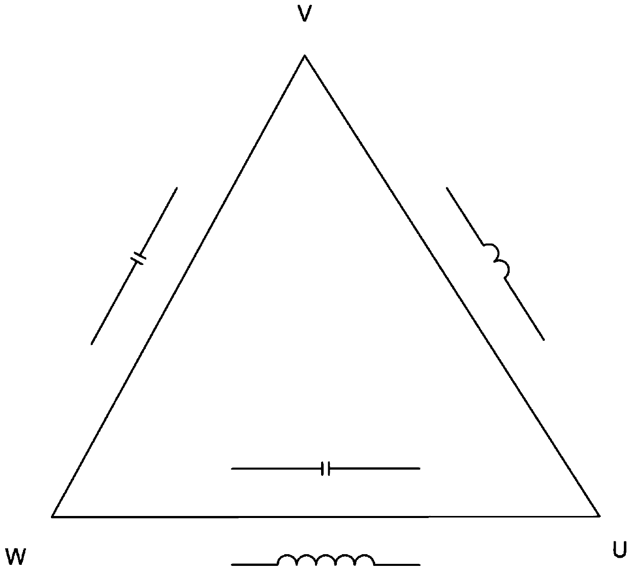
[0019] Such as image 3 , 4 As shown, it is to realize a "static balance and dynamic compensation device for double-coil power frequency induction conjoined furnace" that can meet the two working modes of melting and heat preservation of horizontal continuous casting equipment, so as to avoid the phase-to-phase imbalance of power supply current and the The phenomenon of low power factor or overcompensation. Including sensors, PLC controllers, and actuator controllers. The sensors are used to collect parameters of three-phase electricity, and their output terminals are connected to the PLC controller. The output terminals of the PLC controller are connected to the input terminals of the actuator controller. The output end of the switch is connected with a plurality of contacto...


PUM


Abstract

The invention discloses an automatic power factor compensation device for double-coil power frequency induction connected furnaces, which comprises a sensor, a PLC controller and an actuator controller. The sensor is used for collecting the parameters of three-phase electricity. The output terminal of the sensor is connected with the PLC controller. The output terminal of the PLC controller is connected with the input terminal of the actuator controller. The output terminal of the actuator controller is connected with a plurality of contactors, each of which correspondingly controls the switching of one set of compensation capacitors. The compensation capacitors are used for making compensation for the three-phase electricity. The advantage is that capacitor switching is automatically controlled by detecting data, so that the change of a double-coil connected furnace between two gears is satisfied, the device can better adapt to connected furnaces, and inter-phase current balance and power factor compensation are achieved during working of connected furnaces.

Description

technical field [0001] The invention relates to the technical field of non-ferrous metal smelting, in particular to an automatic power factor compensation device for a double-coil power frequency induction conjoined furnace. Background technique [0002] The double-coil power-frequency induction conjoined furnace is one of the main equipments used by single-material non-ferrous metal rolling enterprises for melting and mold traction forming. Because the double-coil power-frequency induction conjoined furnace has high thermal efficiency and electric The advantages of high efficiency, less metal loss, uniform temperature in the furnace and stable furnace temperature have been widely used in the production of some metallurgy and non-ferrous metal rolling industries. [0003] Although the use of the double-coil power frequency induction conjoined furnace has many advantages, there are still several technical problems in the process of using the double-coil power frequency induct...

Claims


Application Information

Patent Timeline
Patent Type & Authority Applications(China)
IPC IPC(8): H02J3/18
CPCH02J3/1864Y02E40/30
Inventor 谢维维吴昌智
Owner ANHUI YONGJIE COPPER
Why Eureka
Try Eureka